Project Info
Author: Chris
Difficulty: Medium
Time Invested: 3 Hours
Prerequisites:
Take a look at the above
articles before continuing
to read this article.
Author: Chris
Difficulty: Medium
Time Invested: 3 Hours
Prerequisites:
Take a look at the above
articles before continuing
to read this article.
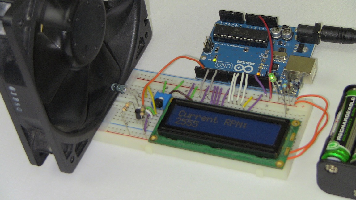
In this article we will explore how to use an IR transmitter and receiver break-beam pair similar to the PIC Tachometer project I built a few months ago, but because of popular demand, the Arduino system will be used for all the processing and break-beam interruption counting. The end result will be a 16x2 LCD displaying the RPM of some computer fans.
Purpose & Overview Of This Project
The purpose of this project is to build a single input, single output system. The input will come in the form of a signal state change from high (+5v) to low (+0v) which will occur when the IR break-beam is interrupted and the Arduino will then increment an internal counter. As time goes on, additional processing and calculation will occur as interrupts are trigger and the LCD will output the calculated RPM.
To create the IR break-beam, we will used an IR LED with a low value resistor so that it shines very bright. The receiver will be a phototransistor which biases 'on' whenever the IR LED's light is detected. A computer fan will be placed between the IR link and turned on so as to continuously generate an interrupt through some additional transistor logic circuitry. For output, the Arduino LCD interface that we saw last week will be used so that we can output the final RPM value to the LCD.