Schematic Overview
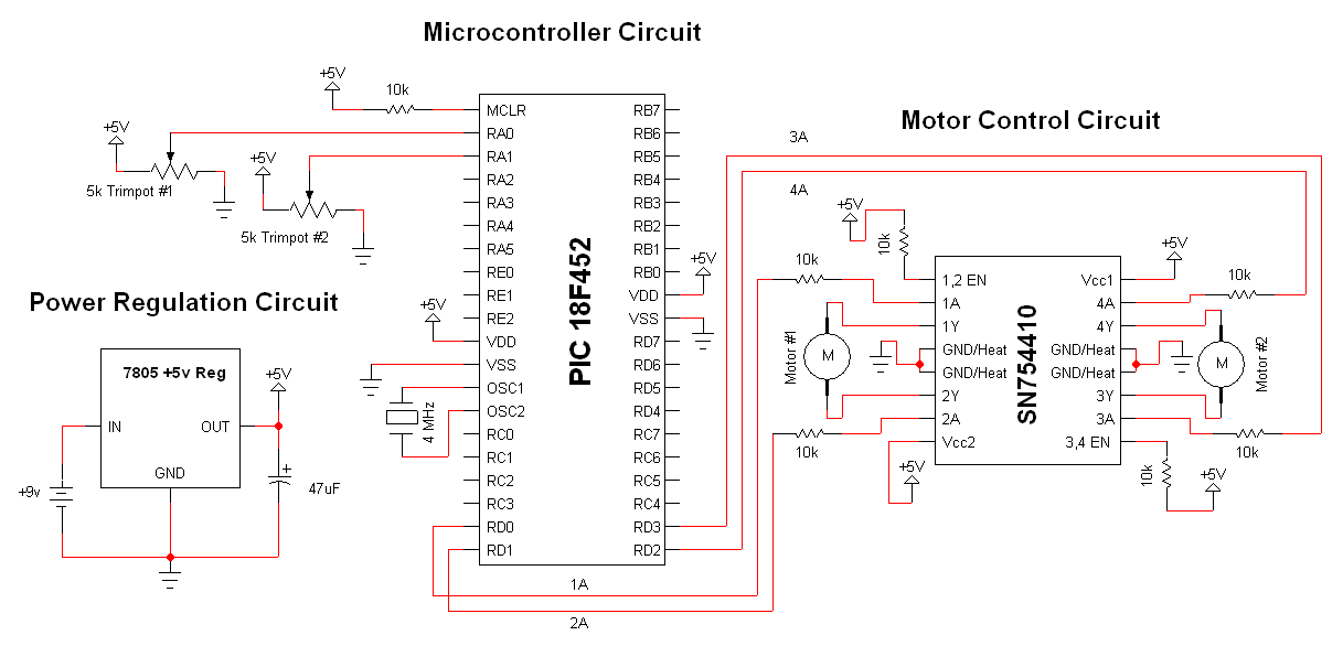
The SN754410 Dual Motor Control circuit can be seen below. It is just about as simple as it looks with the PIC being the central processor. The main parts used and seen in the schematic below are the 7805, 18F452 and SN754410.
View Full Schematic
Schematic Specifics
Power Regulation Circuit
The LM7805 +5v Regulator is used for its simplicity and the fact that the PIC uses the +5v digital standard. Since our motors are not too current demanding, this regulated supply will also be connected to the motor controller.
Microcontroller Circuit
The PIC 18F452 acts as the primary input and output control unit. It will be taking the analog input from PORTA pins 2 (RA0) and 3 (RA1), evaulating this input and then using PORTD, pins 19, 20, 21 and 22 to tell the motor controller what motors to move where and how fast.
Motor Control Circuit
The Motor Controller has 4 input pins 1A, 2A, 3A and 4A. The corresponding output pin for each half-h-bridge is marked with a Y (i.e. 2Y). The digital supply will be used for both signal and motor control so Vcc1 and Vcc2 are tied to the +5v regulated power. Finally, two Enable pins (pin 1 and pin 16) are connected to +5v through a 10kΩ resistor so these h-bridges are always enabled. You could alternatively connect this to an I/O pin on the PIC to control these enable bits, but for simplicity I have not done that here.