Hardware Design
Since the hardware design is already completed, all that is left is to actually build the circuit. Here I will document the process of putting all the parts onto the breadboard. Just follow the schematic!
Building The Circuit
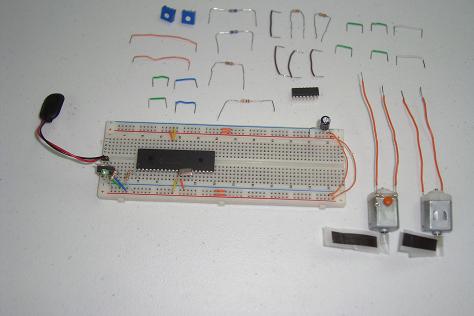
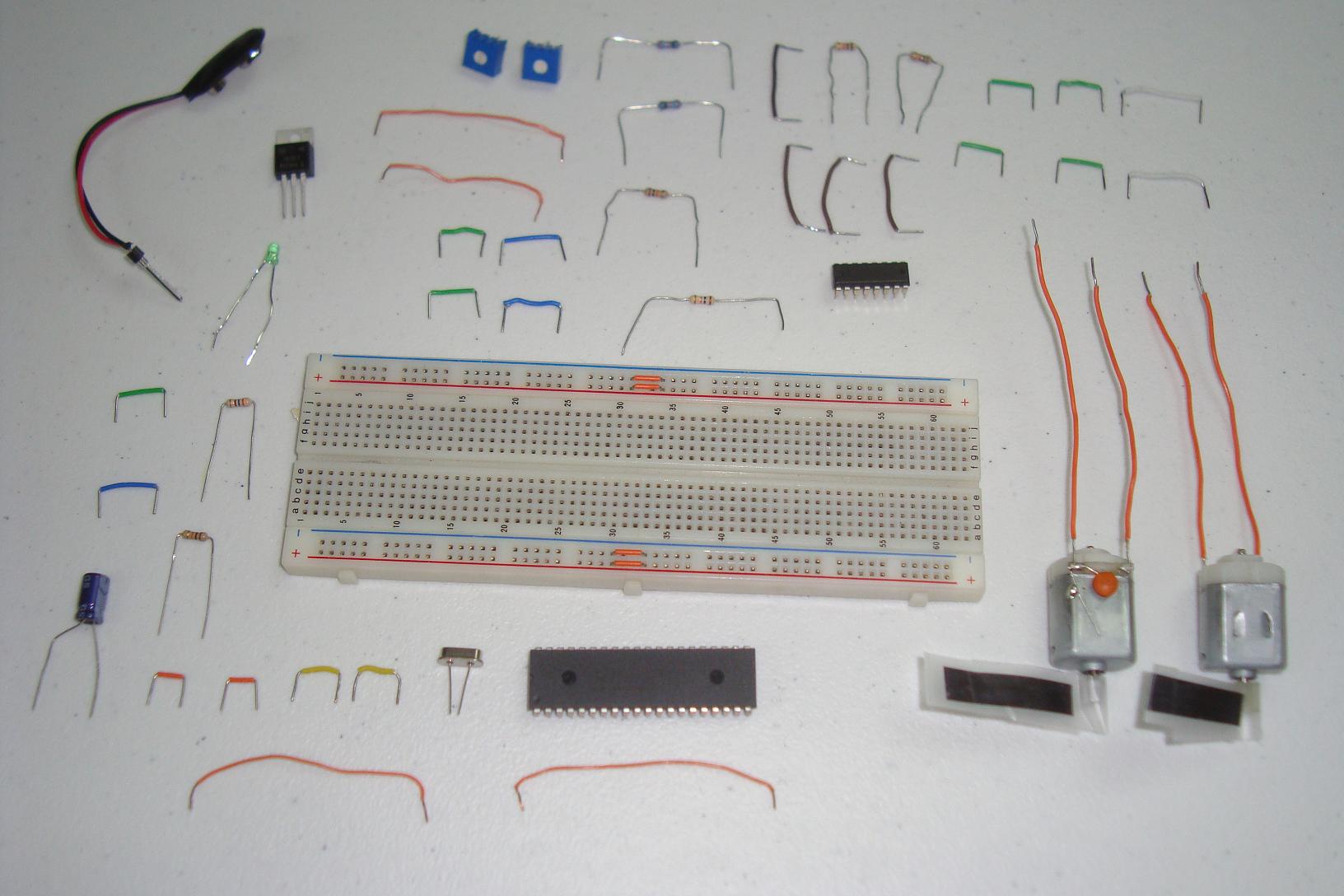
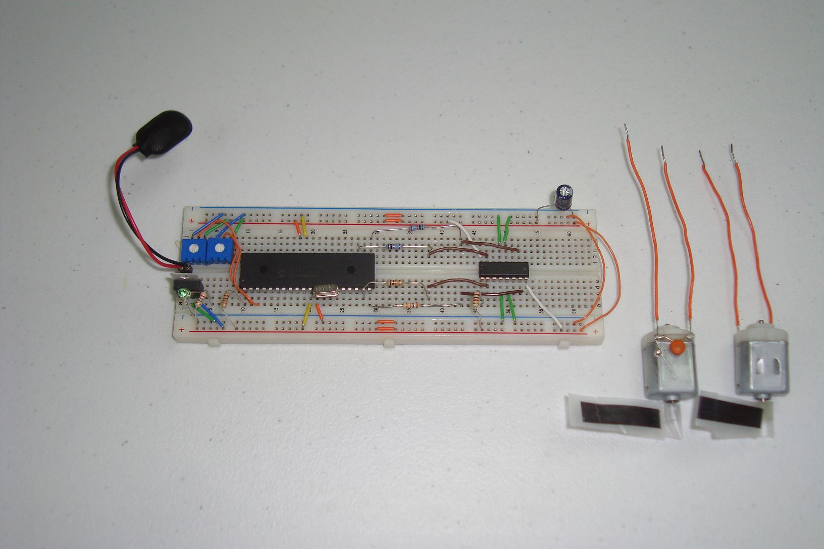
Here you can see all of the parts used in the circuit for this motor control tutorial.

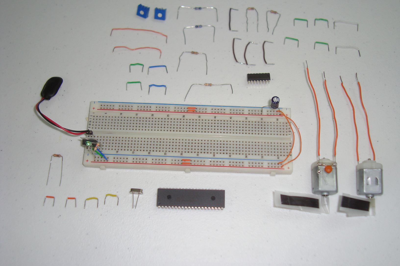
·First the power regulation circuit is assembled. 7805, LED and Capacitor.

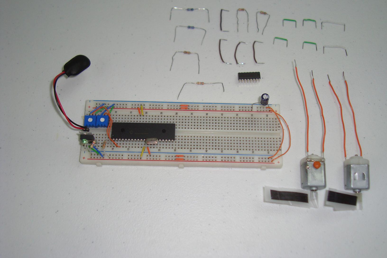
·Next the PIC circuit is connected. 18F452, 10k Resistor and 4 MHz Clock.
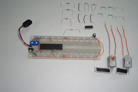
·The 5k Trimpots are connected to the PIC's input at PORTA, RA0 and RA1.
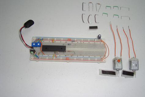
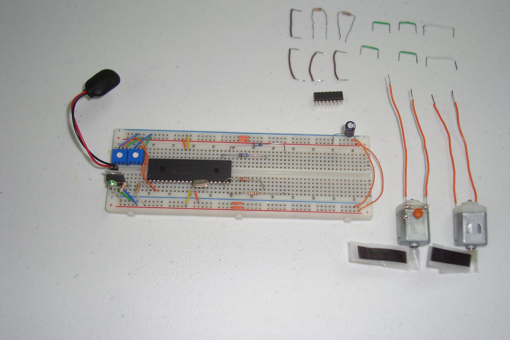
·Next, 4x 10k Resistors are connected to the output at RD0, RD1, RD2 and RD3.
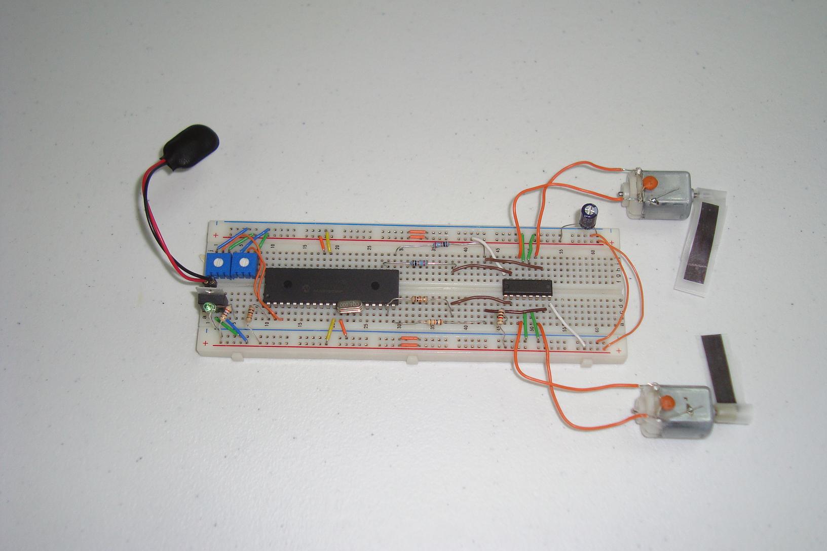
·The motor control circuit is connected together. Take your time here and get it done correctly!
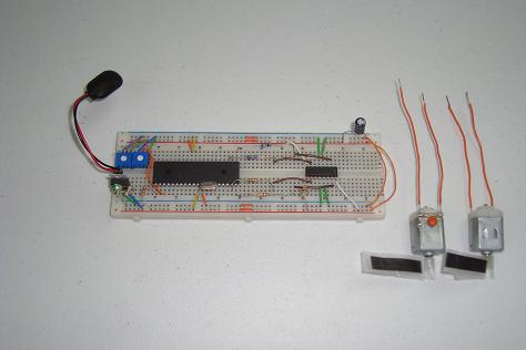
·Finally, the motors are connected to the output from the SN754410.

·With the hardware wired up and completed, let's take a look at the software.
Since the hardware design is already completed, all that is left is to actually build the circuit. Here I will document the process of putting all the parts onto the breadboard. Just follow the schematic!
Building The Circuit
Here you can see all of the parts used in the circuit for this motor control tutorial.
·First the power regulation circuit is assembled. 7805, LED and Capacitor.
·Next the PIC circuit is connected. 18F452, 10k Resistor and 4 MHz Clock.

·The 5k Trimpots are connected to the PIC's input at PORTA, RA0 and RA1.
·Next, 4x 10k Resistors are connected to the output at RD0, RD1, RD2 and RD3.
·The motor control circuit is connected together. Take your time here and get it done correctly!
·Finally, the motors are connected to the output from the SN754410.
·With the hardware wired up and completed, let's take a look at the software.