There are two main portions of code that we are concerned with:
-Opening The Serial USART Comm.
-Receiving, Executing the Command
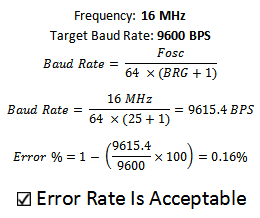
The first portion of the code I want to share with you is how to setup the PIC's built in hardware USART. It requires a few specific functions that can set it up many different ways. The most important of which is how to calculate the communication speed, baud rate:
Opening The Serial USART Comm.
------------« Begin Code »------------
..
....
....

OpenUSART( USART_TX_INT_OFF &
			USART_RX_INT_OFF &
			USART_ASYNCH_MODE &
			USART_EIGHT_BIT &
			USART_CONT_RX &
			USART_BRGH_LOW,
			25 );
....
..
..
------------« End Code »------------
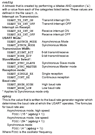
This single function determines whether interrupts are triggered on a full 8 bit receive or transmit, what type of communication 8-bit or 9-bit, what type of reception (continuous,single) and the baud rate. The C18 libraries define these properties in detail:
Receiving and Executing Commands
------------« Begin Code »------------
..
...
while(1){
    //If New Character Input, Update Output Buffer Value
    if(previous_input_buf != current_input_buf){
        switch(current_input_buf){
            case '0' : output_buf = 0x00;
                input_set=1;
                break;
    ..
    ...
    ..
        }
    }
    //Update PORTB LED Outputs
    PORTB = output_buf;
    Delay10KTCYx(20);
    current_input_buf = getcUSART();
}
...
..
------------« End Code »------------
The hardware USART in the PIC takes care of all the low-level reception work and so we will use a short polling routine to see when new data arrives. When new data has arrived (previous_character != current_character) the correlating command is executed through the switch statement. This loop continues over and over, forever until the battery dies out. There you have it, the software for a simplistic serial rs232 interface, now let's test it out!