Schematic Overview
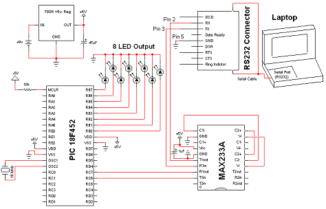
The circuit for the rs232 serial interface is of mild complexity. The main parts of the circuit are the 18F4520, MAX233A and DB-9 Connector and these portions of the circuit will be described briefly below.
View Full Schematic
Schematic Specifics
Power Circuit
This is a basic +5v power regulator circuit for the digital signals/components. All components in this circuit use this regulated +5v for power. The input is simply from a +9v battery.
Microcontroller Circuit
The PIC has two man chores for this circuit. The first is receiving and sending RS232 serial communication commands and the second is turning off and on specific LEDs depending on which command is received.
MAX233A Circuit
The MAX233A IC acts more like a translator for going from the digital +5v/+0v and into the RS232 +12v/-12v signals. This 'translation' is necessary in order to create the proper RS232 signals for the receiver to understand. Outgoing Signals are translated through the TXin/TXout and incoming signals are translated through the RXin/RXout pins.
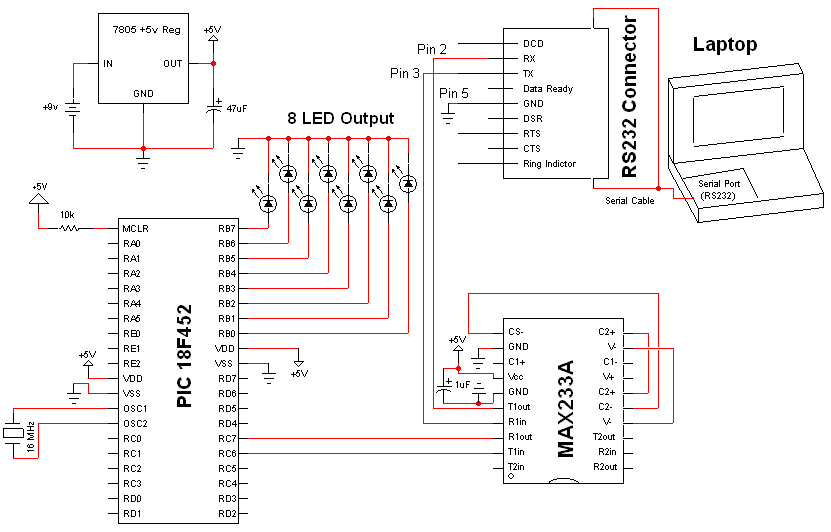