Hardware Design
In the last few parts we looked at the schematic and closer at the IR circuit, now it's time to put it all together-the fun part. The wiring should not be too difficult if you've done other similar projects, or at least wired up a L298 before.
Creating The Optical Encoder Strip & Stage Circuit
The first thing we'll make is an optical encoder strip. To make this all you need is a blanke piece of white paper, a ruler, a pencil and a sharpee black pen:
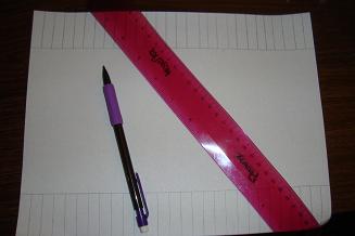
·First draw out your encoder lines. 1/8'' should be fine but you can chose whatever length you want. This will determine how accurate your movements can be.
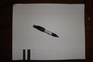
·When you're ready start filling in the squares with sharpee black ink.
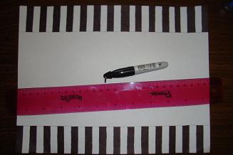
·You should have everything filled in now. Cut the strips from the piece of paper.
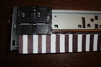
·Now align the strips up on the bottom part of your stripped printer stage.
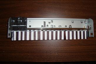
·I used some black electrical tape to hold everything onto the metal case.
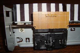
·Now screw on your IR Detector/Emitter setup to the printer stage.
·You will need to align the Emitter/Detector so that they are angled correctly.
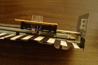
·Here is a simple close up shot of how I have them aligned over the encoder strip.

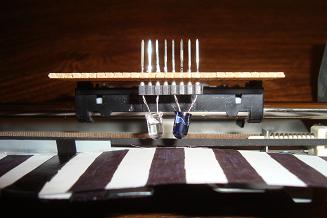
·A far away shot as well. ** Hurray! The first part is finished.
In the last few parts we looked at the schematic and closer at the IR circuit, now it's time to put it all together-the fun part. The wiring should not be too difficult if you've done other similar projects, or at least wired up a L298 before.
Creating The Optical Encoder Strip & Stage Circuit
The first thing we'll make is an optical encoder strip. To make this all you need is a blanke piece of white paper, a ruler, a pencil and a sharpee black pen:
·First draw out your encoder lines. 1/8'' should be fine but you can chose whatever length you want. This will determine how accurate your movements can be.
·When you're ready start filling in the squares with sharpee black ink.
·You should have everything filled in now. Cut the strips from the piece of paper.
·Now align the strips up on the bottom part of your stripped printer stage.
·I used some black electrical tape to hold everything onto the metal case.
·Now screw on your IR Detector/Emitter setup to the printer stage.
·You will need to align the Emitter/Detector so that they are angled correctly.
·Here is a simple close up shot of how I have them aligned over the encoder strip.
·A far away shot as well. ** Hurray! The first part is finished.