Project Info
Author: Chris
Difficulty: Easy-Medium
Time Invested: 4 Hours
Prerequisites:
Take a look at the above
tutorials before continuing
to read this tutorial.
Author: Chris
Difficulty: Easy-Medium
Time Invested: 4 Hours
Prerequisites:
Take a look at the above
tutorials before continuing
to read this tutorial.
The optical encoder will be a black and white paper made using a piece of printer paper and a sharpee pen. Then we will use an IR emitter and detector to keep track of the current location.
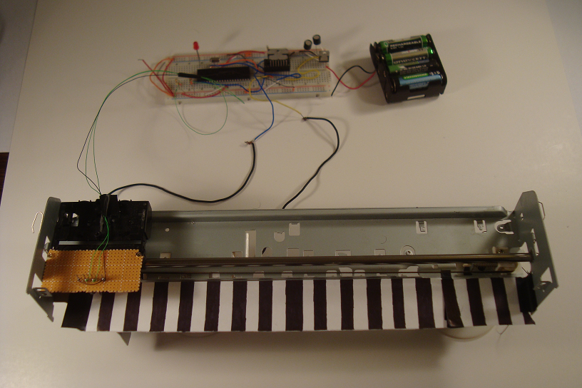

Purpose & Overview of this project
The goal of this tutorial is to create a way to know where the 'stage' is, accurate to about 1/4'' using optical encoding. The stage is controlled via a 12v motor so we will use an L298 motor controller for controlling the motor via a 18F4520 PIC.
The PIC will use hardware PWM generators to output the correct frequency & duty cycle. The PIC will also take the analog input from the IR detector diode to keep track of how far the stage has moved via an internal analog to digital converter (ADC).