Schematic Overview
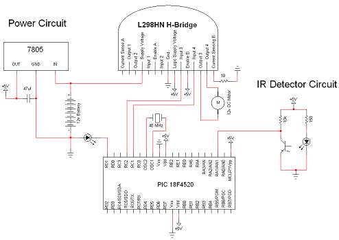
The simple motor optical encoder circuit is not terribly difficult however it will take some double checking to make sure you have everything hooked up properly before working the first time. The main devices used in the circuit are the 7805, 18F4520 and L298HN.
View Full Schematic
Schematic Specifics
Power Circuit
This is a basic +5v power regulator circuit for the digital signals/components. This +5v is also fed to the IR detector circuit. A 7805 device is used for regulating. This a very common +5v regulator and can be found at nearly any manufacturer.
Microcontroller Circuit
The PIC has two man chores for this circuit. (1) It is controlling the motor through RC1 & RC2 which are outputing PWM signals. RC1 outputs a certain PWM signal and RC2 outputs the exact inverse. (2) The PIC is also getting data from the IR detector circuit. Namely the voltage at the output. The change in voltage at the point will tell us whether the optical encoder sees black or white.
IR Detector Circuit
This is as simple as it gets for IR detector circuits. We use two resistors and the two IR components with a power supply. The IR LED shines onto the encoder paper we will build and the IR detector gets the reflected signal.
L298 Motor Control Circuit
The L298 will receive all its commands from the PIC microcontroller at input 3 and input 4. I chose to make Enable B always enabled just so there would be less programming in the PIC. The motor controller is also directly hooked up to the 12v battery supply voltage as well as the +5v supply for the digital signals.
The simple motor optical encoder circuit is not terribly difficult however it will take some double checking to make sure you have everything hooked up properly before working the first time. The main devices used in the circuit are the 7805, 18F4520 and L298HN.

View Full Schematic
Schematic Specifics
Power Circuit
This is a basic +5v power regulator circuit for the digital signals/components. This +5v is also fed to the IR detector circuit. A 7805 device is used for regulating. This a very common +5v regulator and can be found at nearly any manufacturer.
Microcontroller Circuit
The PIC has two man chores for this circuit. (1) It is controlling the motor through RC1 & RC2 which are outputing PWM signals. RC1 outputs a certain PWM signal and RC2 outputs the exact inverse. (2) The PIC is also getting data from the IR detector circuit. Namely the voltage at the output. The change in voltage at the point will tell us whether the optical encoder sees black or white.
IR Detector Circuit
This is as simple as it gets for IR detector circuits. We use two resistors and the two IR components with a power supply. The IR LED shines onto the encoder paper we will build and the IR detector gets the reflected signal.
L298 Motor Control Circuit
The L298 will receive all its commands from the PIC microcontroller at input 3 and input 4. I chose to make Enable B always enabled just so there would be less programming in the PIC. The motor controller is also directly hooked up to the 12v battery supply voltage as well as the +5v supply for the digital signals.