Hardware Design
Since the hardware being designed is actually the FPGA VHDL module, we'll save that for the software section. This hardware section will show you the semi-quick process of wiring everything up and getting the LCD, Power Supply Board and FPGA ready for business.
·I used a bunch of breadboard wires to connect the two ribbon cables. Doing this was quicker than making a small pcb, although not as reliable.
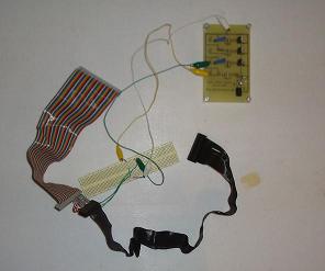
·Next I connected th +5v, +3.3v and GND pins to the LCD connector (rainbow colored ribbon cable).
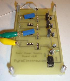
·Here you can see the 3 alligator clips used to power the lcd connected to the power supply board.
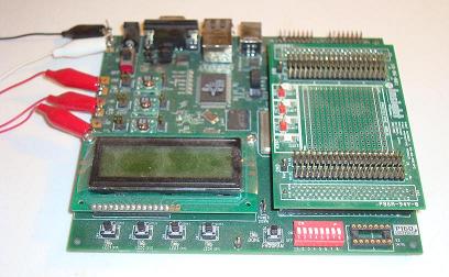
·This is the FPGA board used for this tutorial. It has a virtex 4 onboard. The 4 alligator clips connect GND, +5v, +3.3v, +2.5v and +1.25v from the power supply board.
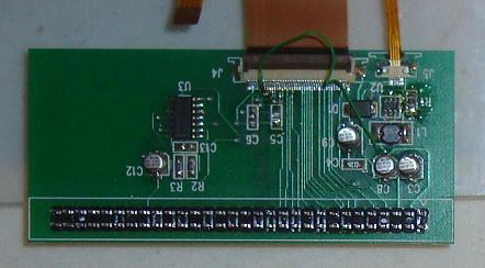
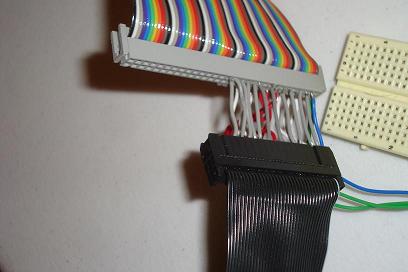
·This is the back side of the LCD connector board. The rainbow colored ribbon cable will connect here. The board doesn't do anything special except make it so that its easy to get to each individual pin on the LCD.
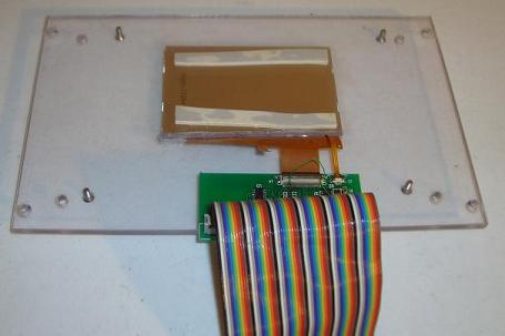
·The ribbon cable is connected to the LCD board.
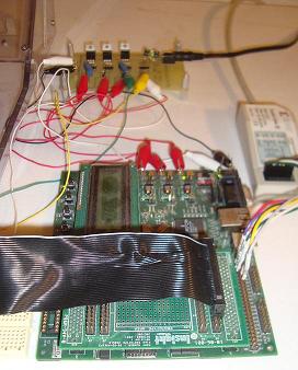
·Similarly, the other end of the cable, which is a standard floppy drive ribbon cable is connected to the FPGA board I/O ports.
·A top view of the FPGA Board/FPGA Programmer/Power Supply Board all connected together.
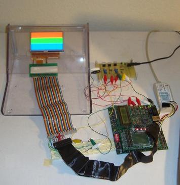
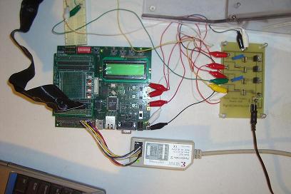
·This is what the final setup looks like while running the FPGA VHDL code. Continue to the software section to see how to do this.
Since the hardware being designed is actually the FPGA VHDL module, we'll save that for the software section. This hardware section will show you the semi-quick process of wiring everything up and getting the LCD, Power Supply Board and FPGA ready for business.
·I used a bunch of breadboard wires to connect the two ribbon cables. Doing this was quicker than making a small pcb, although not as reliable.
·Next I connected th +5v, +3.3v and GND pins to the LCD connector (rainbow colored ribbon cable).
·Here you can see the 3 alligator clips used to power the lcd connected to the power supply board.
·This is the FPGA board used for this tutorial. It has a virtex 4 onboard. The 4 alligator clips connect GND, +5v, +3.3v, +2.5v and +1.25v from the power supply board.
·This is the back side of the LCD connector board. The rainbow colored ribbon cable will connect here. The board doesn't do anything special except make it so that its easy to get to each individual pin on the LCD.
·The ribbon cable is connected to the LCD board.
·Similarly, the other end of the cable, which is a standard floppy drive ribbon cable is connected to the FPGA board I/O ports.
·A top view of the FPGA Board/FPGA Programmer/Power Supply Board all connected together.
·This is what the final setup looks like while running the FPGA VHDL code. Continue to the software section to see how to do this.