Solder Sips Onto The LCD
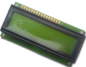
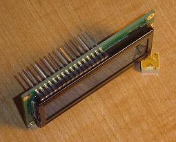
The LCD has 16 spots for sips and they fit right in. The first picture shown below is the LCD alone & bare. This is what it looks like when you first purchase it. The second picture shows an LCD with sips soldered onto the 16 spots. Now we can easily access the 16 pins to tell the LCD what to do!
Before Soldering In Sips
After Soldering In Sips
Wirewrap The LCD To The PIC
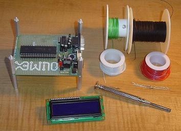
Now we'll actually connect the sips from the LCD to the pins of the pic seen in the schematic. This should be a straight-forward process if you have wirewrapping experience. The tools in the above picture were used to wirewrap.
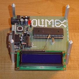
It's important to note that I didn't bother wirewrapping the two resistors, I juse connected them using the sips. The 1.2k ohm resistor was connnected to the GND pin on the LCD itself and the 50 ohm resistor was connected across to the pic's VCD pin.

The last picture shows the wirewrap job that I did. Not too many wires luckily which makes adding LCDs to projects easy to do. Hardware done! Let's take a look at the software.
The LCD has 16 spots for sips and they fit right in. The first picture shown below is the LCD alone & bare. This is what it looks like when you first purchase it. The second picture shows an LCD with sips soldered onto the 16 spots. Now we can easily access the 16 pins to tell the LCD what to do!
Before Soldering In Sips
After Soldering In Sips
Wirewrap The LCD To The PIC
Now we'll actually connect the sips from the LCD to the pins of the pic seen in the schematic. This should be a straight-forward process if you have wirewrapping experience. The tools in the above picture were used to wirewrap.
It's important to note that I didn't bother wirewrapping the two resistors, I juse connected them using the sips. The 1.2k ohm resistor was connnected to the GND pin on the LCD itself and the 50 ohm resistor was connected across to the pic's VCD pin.
The last picture shows the wirewrap job that I did. Not too many wires luckily which makes adding LCDs to projects easy to do. Hardware done! Let's take a look at the software.