Hardware Design
The hardware for this project consists of only a few parts, so we'll take a close look at all of them and see how everything is setup.
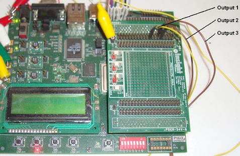
The NTSC signals will come from the FPGA board in digital form. They will be either 3.3v or 0v. The VHDL code seen in the next section will give you a better idea of exactly how the signals are created and when they are ouput.

We need to change the digital signals coming from the FPGA board into lower level 'analog' signals in order for the NTSC protocol to work decently. Using the voltage divider seen above, we create the 0.3v signal for the horizontal/veritcal syncing and 0.5v signal for the lowest color intesity during the data ouput.
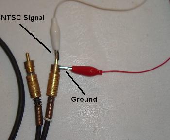
From the breadboard and voltage divider circuit, the mixed NTSC signal goes to a standard RCA AV cable. On the connector, the outside circular portion is ground and the inside prong sticking out is where you connect the signal. Notice I've used alligator clips for transferring most of the signals. Alligator clips will work, but they're only good for these kinds of quick and dirty experiments. Please don't use them in a professional setting!
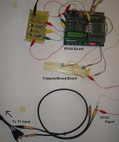
Finally we connect the other side of the RCA A/V cable to a TV and see the results that come out. This really isn't a physically hardware intensive project, however the signal we're creating is extremely delicate and susceptible to noise. Mixing it in some breadboards or using excessing alligator clips might mess up the signal and make is unuseable, so take care!
The hardware for this project consists of only a few parts, so we'll take a close look at all of them and see how everything is setup.
The NTSC signals will come from the FPGA board in digital form. They will be either 3.3v or 0v. The VHDL code seen in the next section will give you a better idea of exactly how the signals are created and when they are ouput.
We need to change the digital signals coming from the FPGA board into lower level 'analog' signals in order for the NTSC protocol to work decently. Using the voltage divider seen above, we create the 0.3v signal for the horizontal/veritcal syncing and 0.5v signal for the lowest color intesity during the data ouput.
From the breadboard and voltage divider circuit, the mixed NTSC signal goes to a standard RCA AV cable. On the connector, the outside circular portion is ground and the inside prong sticking out is where you connect the signal. Notice I've used alligator clips for transferring most of the signals. Alligator clips will work, but they're only good for these kinds of quick and dirty experiments. Please don't use them in a professional setting!
Finally we connect the other side of the RCA A/V cable to a TV and see the results that come out. This really isn't a physically hardware intensive project, however the signal we're creating is extremely delicate and susceptible to noise. Mixing it in some breadboards or using excessing alligator clips might mess up the signal and make is unuseable, so take care!