Project Info
Author: Chris
Difficulty: Medium
Time Invested: 2 Hours
Prerequisites:
Take a look at the above
tutorials before continuing
to read this tutorial.
Author: Chris
Difficulty: Medium
Time Invested: 2 Hours
Prerequisites:
Take a look at the above
tutorials before continuing
to read this tutorial.
I²C is unique in that it only requires 3 wires: Data, Clock and Ground. This is because data is sent and received on the same wire/pin. Clock speeds can be 100 KHz, 400 KHz or even faster, which is faster than standard RS232 but slower than USB.
Purpose & Overview of this project
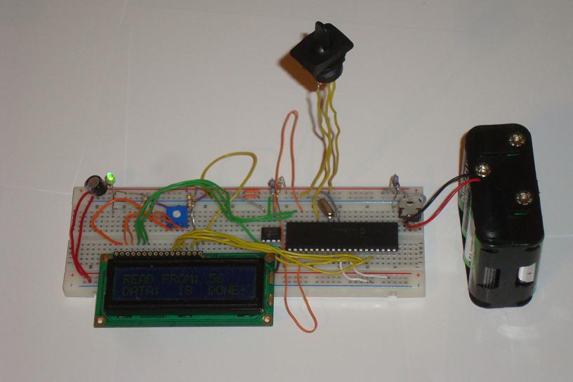
This tutorial will cover the basics of the I²C communication protocol. The theory section will describe the Start/Stop sequence as well as the Data/Address send and receive functionality. For the working exmaple a standard I2C memory device will be used as the slave device and the PIC18F452 will be used as the master device.
The example design should use a switch to go back and forth from 'read' mode to 'write' mode. When write mode is activated:
- [1] A random number will be generated
- [2] It will be output to the LCD
- [3] Use I2C interface to write the number to the memory device
Specifically, the random number will be written to the memory location 56 or 0x38. Similarly, everytime the 'read 'mode is selected:
- [1] Use I2C interface to read from the memory device
- [2] then output data value received to the LCD.