The Theory
The basic communication theory for I2C is that the 'Master' device must initiate any response from a 'Slave' device by calling out it's device ID and then giving an Address, Data or Command. The slave device responds with the requested value. This theory will be explained below.
I2C Communication: Start/Stop
The I2C communication sequence is started by the Master device pulling the SDA signal down to +0v as seen below. When this happens all devices on the SDA bus know that one device is about to send information. In the same way that I2C communication is started, it is stopped: the maser pulls the SDA signal back up to +5v meaning the bus cannot be used. Since all communication in standard I2C happens in 9 bit bursts (8 data bits + 1 bit acknowledge), any device using the I2C data bus (SDA pin) knows how many bits should be seen and when.
I2C Communication: Master Read Request
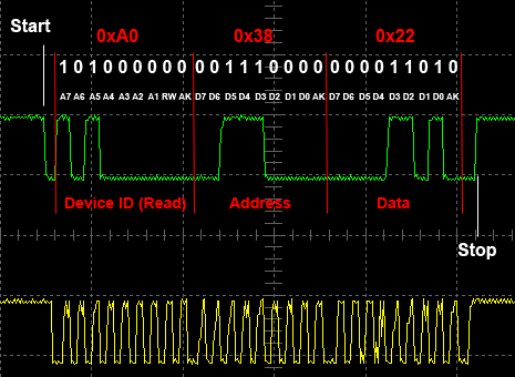
Here Is the read sequence:
The basic communication theory for I2C is that the 'Master' device must initiate any response from a 'Slave' device by calling out it's device ID and then giving an Address, Data or Command. The slave device responds with the requested value. This theory will be explained below.
The I2C communication sequence is started by the Master device pulling the SDA signal down to +0v as seen below. When this happens all devices on the SDA bus know that one device is about to send information. In the same way that I2C communication is started, it is stopped: the maser pulls the SDA signal back up to +5v meaning the bus cannot be used. Since all communication in standard I2C happens in 9 bit bursts (8 data bits + 1 bit acknowledge), any device using the I2C data bus (SDA pin) knows how many bits should be seen and when.
Here Is the read sequence:
- [1] The Master Sets The Start Bit Low
- [2] The Master Write The Device ID + Read/Write Bit
- [3] The Slave Acknowledges With One '0' Bit
- [4] The Master Writes The 8-bit Address To Read
- [5] The Slave Acknowledges With One '0' Bit
- [6] The Slave Writes The 8-Bits At The Address
- [7] The Master Acknowledges With One '0' Bit
- [8] The Master Sets The Stop Bit At 1 (+5v)
- The sequence seen above is the simplest form of the
communication that can happen with an I2C interface. Read through the sequence seen above and how it pertains to the picture a few times and you'll get it.
I2C Communication: Master Write Request
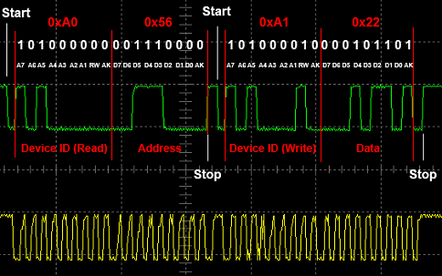
Here Is the write sequence:- [1] Master Sets The Start Bit Low (+0v)
- [2] Master Write The Device ID + Read/Write Bit
- [3] Slave Acknowledges With One '0' Bit
- [4] Master Writes The 8-bit Address To Read
- [5] Slave Acknowledges With One '0' Bit
- [6] Master Sets The Stop Bit At 1 (+5v)
- [7] Master Sets The Start Bit Low (+0v)
- [8] Master Acknowledges With One '0' Bit
- [9] Master Sends 8 data bits
- [9] Slave writes the data to memory
- [10] Master Sets Not-Acknowledge Bit (+5v)
- [11] Master Sets The Stop Bit At 1 (+5v)
- As you can see the write sequence involved two
seperate I2C communications: one to tell the address and one for transferring the data. Again, this is the most simple type of write that you can have.
Page-read and Page write (multiples) can also be done for large amounts of memory.