Schematic Overview
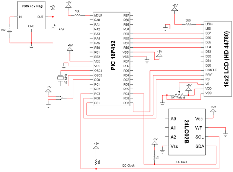
The I2C PIC Interfacing Tutorial circuit is not terribly difficult however it will take some double checking to make sure you have everything hooked up properly before working the first time. The main devices used in the circuit are the 18F452, 24LC02B and 16x2 LCD.
View Full Schematic
Schematic Specifics
Power Circuit
The power circuit uses a LM7805 +5 voltage regualtor. Stick in an voltage over +6.5v and it gets regulated down to +5v with excess power exhausted through the heatsink. This is a standard power circuit that I've used in most all my tutorials, nothing extra-ordinary. here
I2C Interface To PIC
The I2C Interface From PIC to the EEPROM (24LC02B) is 2 wires, SDA and SCL. **Special Note**: The two resistors 1k and 10k connected to +5v are critical if you want your I2C interface to work properly. You must have at least a 10k resistor connected to +5v or nothing will work. This is due to the fact that SCL and SDA are 'open drain', which means I2C devices can drive signals low to +0v but not high to +5v.
4-Bit LCD Interface
The LCD used in this tutorial will only use 4 data-bits, mostly because I was too lazy to use 8 wires and things would start to look too cluttered on a breadboard with that many wires. The 4-bit interface just requires you to send data in two 4-bit sequences instead of in 1 8-bit sequence. Look at the software to see this difference.
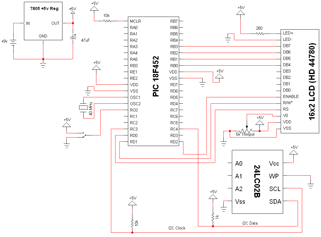