Hardware Design
There is no special hardware design required for this tutorial beyond following the schematic and assembling the circuit on a breadboard. You will have to program the PIC eventually, so keep that in mind.
Building The Circuit
Gather all the parts needed to build the circuit. Since a breadboard is used, building the circuit should be rather painless and shouldn't take too long. The pictures below guide you through the process of hooking up the different portions of the circuit according to the schematic.
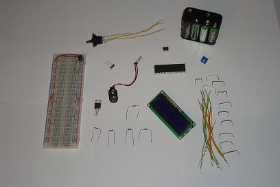
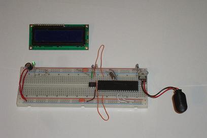
·So first take the few parts for the power circuit.
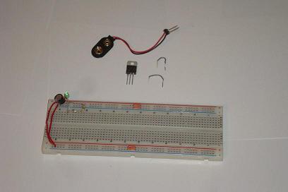
·The 7805 is the core component for regulating the power to +5v.
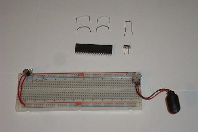
·Next connect the PIC circuit to power and the 40 MHz crystal.
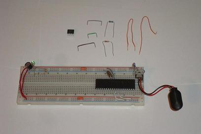
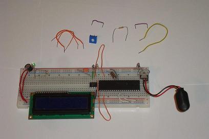
·Now get the parts for the 24LC02B and connect them to the PIC
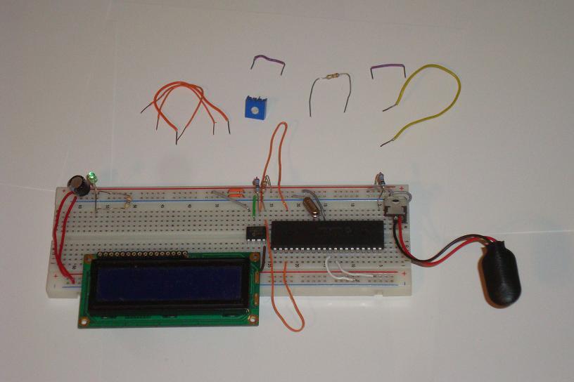
·Next, the LCD needs to go on the board. It has 16 pins.
·Connect the power, intensity and backlight.

·Now the 3 control wires from the LCD to the PIC
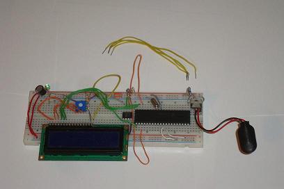
·The last 4 wires connect the LCD data pins to the PIC
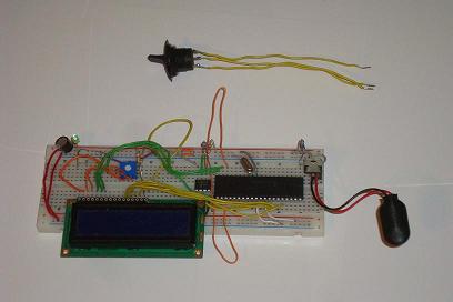
·Lastly, connect the switch to the PIC's PORTC Pin 0.

·Now it's 100% assembled and ready to be programmed and run.
There is no special hardware design required for this tutorial beyond following the schematic and assembling the circuit on a breadboard. You will have to program the PIC eventually, so keep that in mind.
Building The Circuit
Gather all the parts needed to build the circuit. Since a breadboard is used, building the circuit should be rather painless and shouldn't take too long. The pictures below guide you through the process of hooking up the different portions of the circuit according to the schematic.
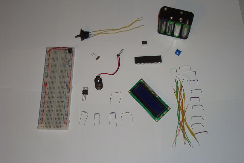
·So first take the few parts for the power circuit.
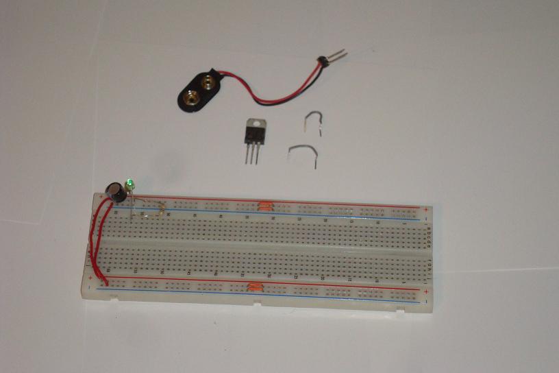
·The 7805 is the core component for regulating the power to +5v.

·Next connect the PIC circuit to power and the 40 MHz crystal.
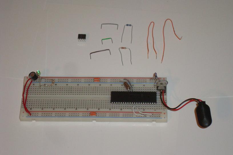
·Now get the parts for the 24LC02B and connect them to the PIC

·Next, the LCD needs to go on the board. It has 16 pins.
·Connect the power, intensity and backlight.
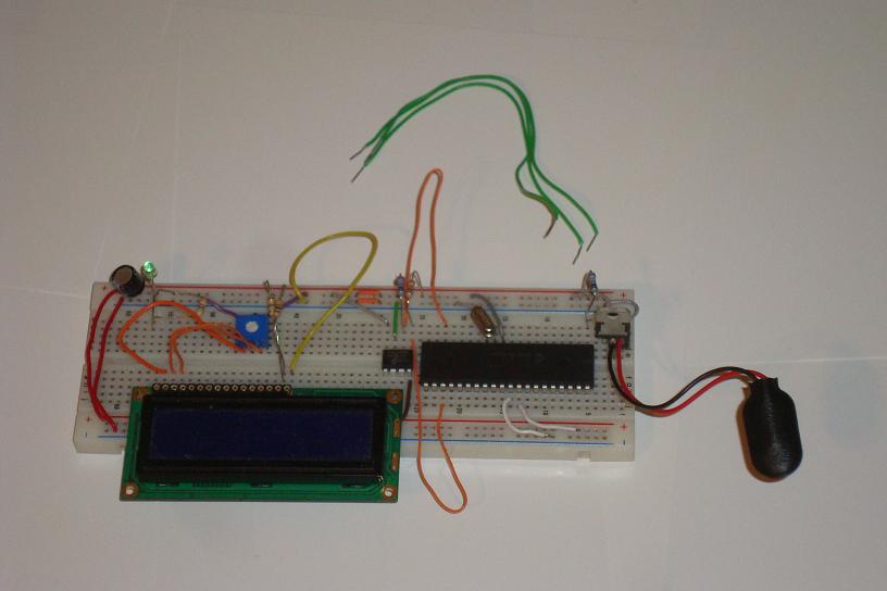
·Now the 3 control wires from the LCD to the PIC
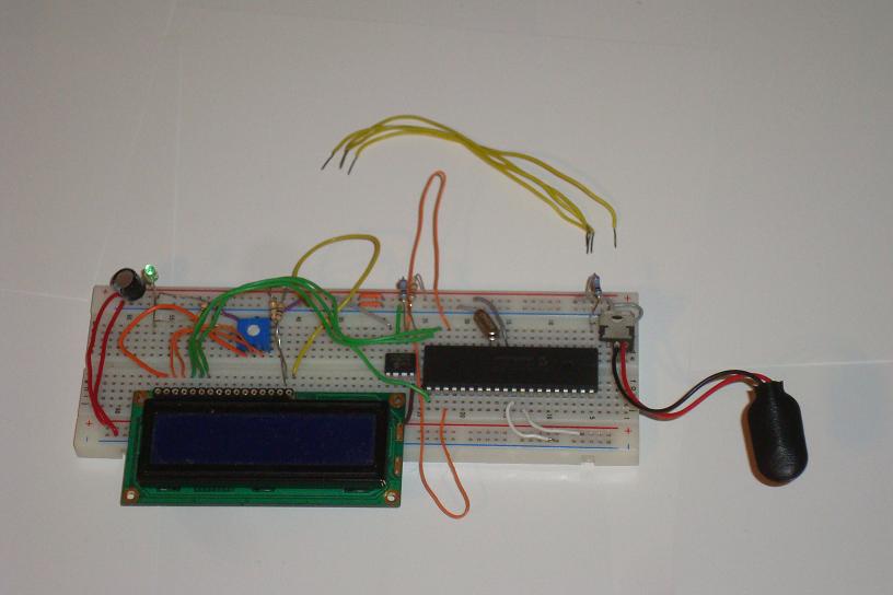
·The last 4 wires connect the LCD data pins to the PIC
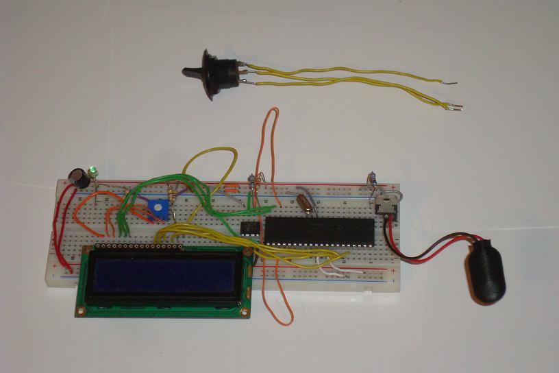
·Lastly, connect the switch to the PIC's PORTC Pin 0.
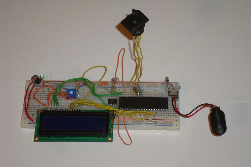
·Now it's 100% assembled and ready to be programmed and run.