With the schematic build, and the board laid out we are ready to make our PCB and build the H-bridge. Making the PCB is the first step of this process so we will do that now. Get your Ferric Chloride etchant and Copper PC Board ready.
PCB Fabrication - DIY Style
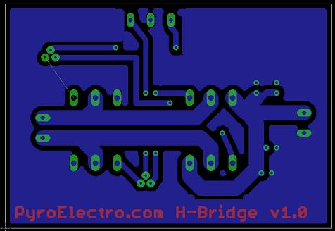
Below is a quick reminder of what the top and bottom sides of the board will look like when finished. If you downloaded the printable PDF above, you'll notice that things are mirrored and not directly the same as the image below. Since we're using the toner transfer process we have to mirror these things to make sure the board isn't all backwards.
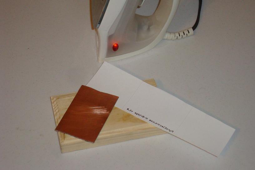
·Print out the layout on some glossy paper and cut it as I have.
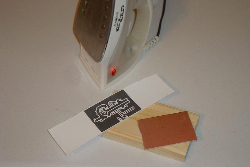
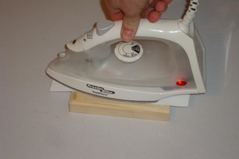
·Place the design face down onto the copper and transfer that toner!
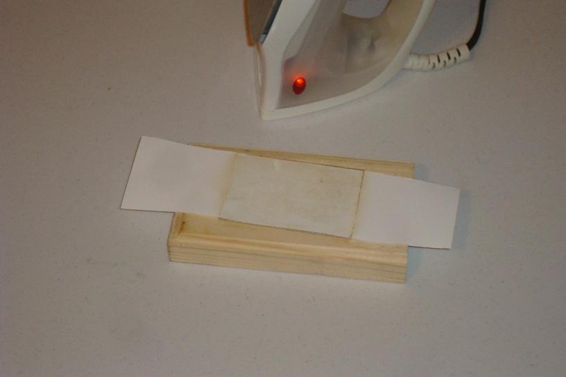
·After a few minutes the toner is transferred. Let's do the 2nd layer.
·Print the top side layout on some glossy paper and get it ready.
·Again, transfer the toner by rubbing the hot iron all over.
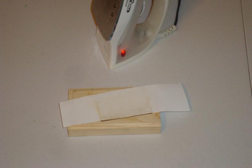
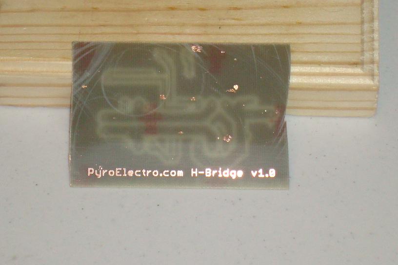
·Rinse with some warm water and you can see the transferred toner.
·Use a felt pen to touch up any spots the toner didn't transfer to.
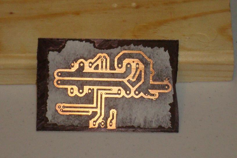
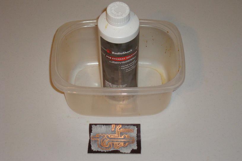
·Use some ferric chloride in a plastic container to etch the copper.
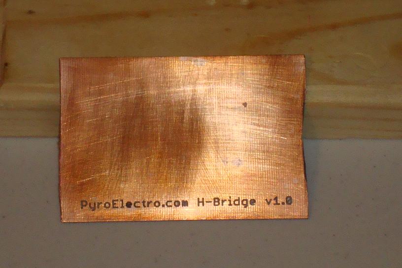
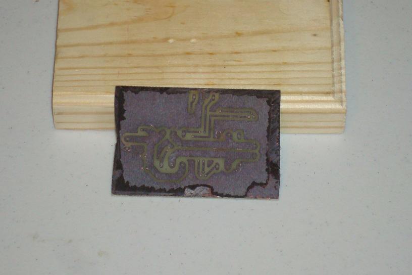
·After etching, the copper is all gone.
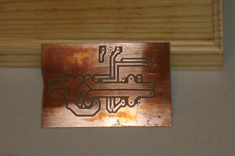
·Clean the toner off with a sponge. Now The Copper is very visible.
·The bottom layer copper is exactly as we designed in the layout.
·Now we are ready to assemble all the parts onto the board.