Project Info
Author: Chris
Difficulty: Medium
Time Invested: 2 Hours
Prerequisites:
Take a look at the above
tutorials before continuing
to read this tutorial.
Author: Chris
Difficulty: Medium
Time Invested: 2 Hours
Prerequisites:
Take a look at the above
tutorials before continuing
to read this tutorial.
This tutorial will take a few steps back from the all-in-one L298 or LMD18245 motor control ICs and look more into how we can build our own H-bridge without the need of an IC.
At first this might sound like a difficult task. How can we, tiny simple people, build something that professional manufacturers put into high power ICs? Well keep reading this tutorial and you'll find out, it's actually easy!
Purpose & Overview of this project
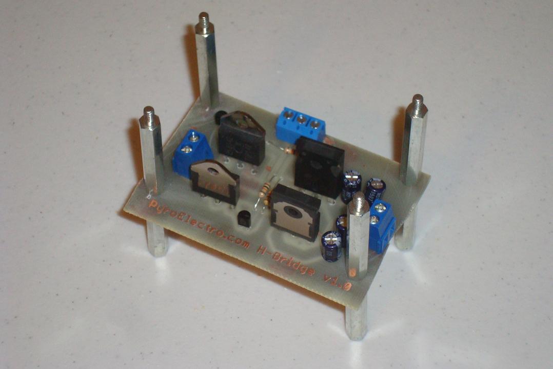
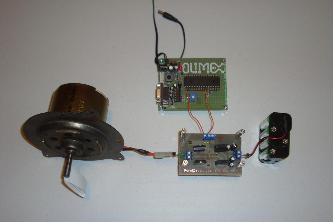
The main goal for this tutorial is to build a 10 AMP motor controller that can control a DC motor with a digital input. This way if we want to use a microcontroller to turn the motor off or on, we can. There should be one digital input for forward and one digital input for backward. Additionally the board should have two terminal blocks, one for the motor's power and one for connecting the H-bridge to the motor.
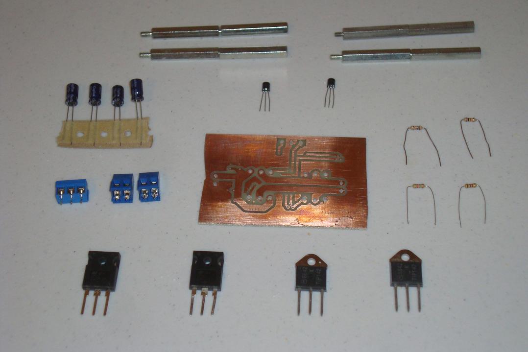
For this design darlington pair BJT power transistors will be used to form the H-bridge. This design choice has pros and cons just like anything, but for our purposes they do the trick. An alternative power transistor that could go higher than 10A would be with HEXFETs. In reality any transistors can be used to form an H-bridge, but their different properties make some better and others terrible.