H-Bridge Hardware Assembly
Luckily the PCB was not so hard to make this time around since we didn't have to align the top and bottom layers. The top layer is just the board name. The next step is the assemble all of the parts for the 10A H-bridge. This means first you have to drill out the holes in the PCB and then solder the parts in.
Building The Circuit
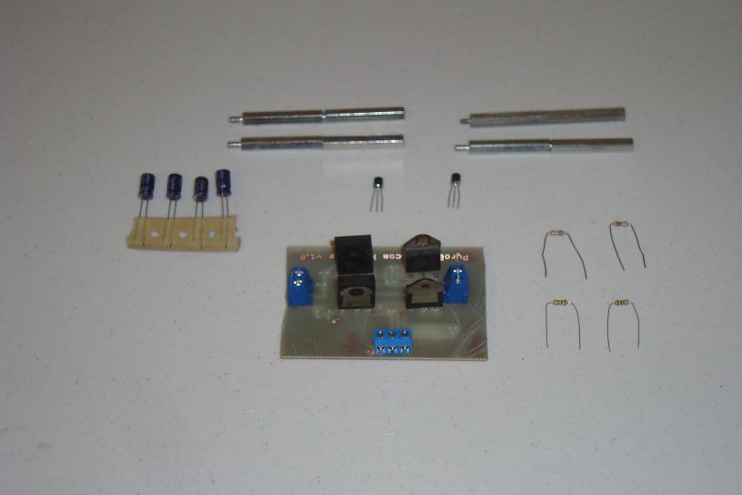
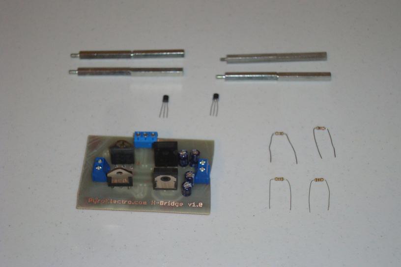
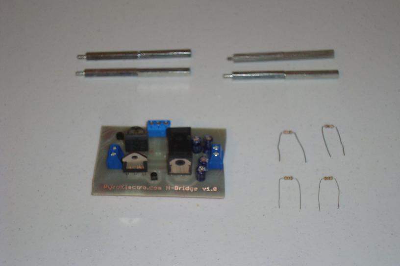
Now, get the parts together and ready to start soldering, the picture below shows everything you need to get the H-bridge put together.
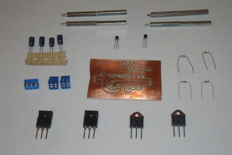
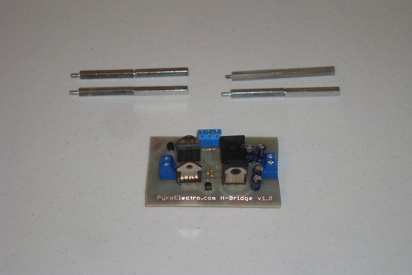
·Take the 4 pwoer BJT transistors and solder them into place.
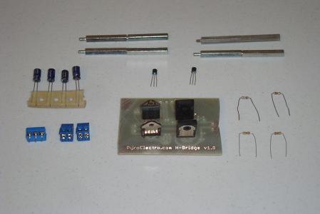
·Solder the dual and triple terminal blocks into the PCB.
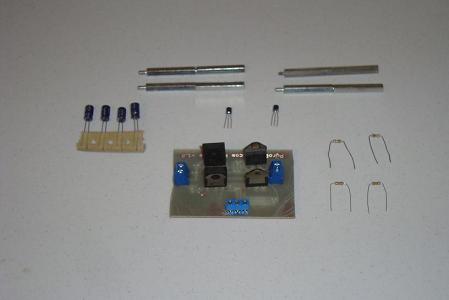
·Now, solder the 4 capacitors into place. Double check the polarity is right!
·Now the 2N2222 transistors can be soldered to the PCB.

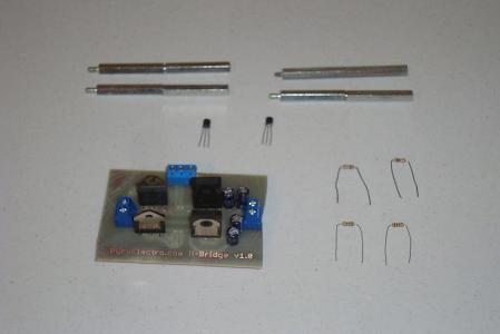
·The four resistors are the last components of the circuit to be soldered.
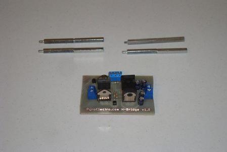
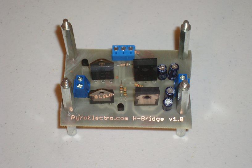
·Now drill 4 holes in the baord for the standoffs and screw them into place.
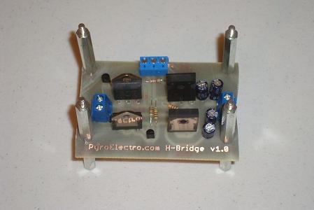
·The 10A H-Bridge is complete and ready for some action, let's test it!
Luckily the PCB was not so hard to make this time around since we didn't have to align the top and bottom layers. The top layer is just the board name. The next step is the assemble all of the parts for the 10A H-bridge. This means first you have to drill out the holes in the PCB and then solder the parts in.
Building The Circuit
Now, get the parts together and ready to start soldering, the picture below shows everything you need to get the H-bridge put together.

·Take the 4 pwoer BJT transistors and solder them into place.

·Solder the dual and triple terminal blocks into the PCB.
·Now, solder the 4 capacitors into place. Double check the polarity is right!
·Now the 2N2222 transistors can be soldered to the PCB.
·The four resistors are the last components of the circuit to be soldered.
·Now drill 4 holes in the baord for the standoffs and screw them into place.
·The 10A H-Bridge is complete and ready for some action, let's test it!