An Overview Of The 10A H-Bridge Motor Controller
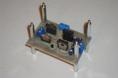
This tutorial went through the theory of how the 4 transistors that form an H-bridge work and how we used them. A few transistors and resistors were added as buffers incase we want to control the motor with additional digital electronics. Overall the H-bridge is a very simple concept that luckily translates to a simple design that can be laid out and built in a single day. Testing is just as simple since not many wires need to be connected beyond power, the motor and control signals.
What To Do Now
Designing your own motor control systems demands that you know what you are doing or else things will get super hot, light on fire or simply not work. Knowing how the basic h-bridge of a motor controller works and building your own puts you on a path to understanding how almost all motor controllers work. This theory will allow you to be a better designer for your future robotics projects or anything that relies on motor control. The paths you can take from here vary tremendously from designing a more power sensitive H-bridge to designing a higher current higher voltage H-bridge for gigantic motors. Go where you want to with this knowledge!
Conclusion
This tutorial's purpose was to show you how DC motor control is done in the real world. While the design presented in this tutorial is about as simple as it gets, it is also present in almost any other motor controller that a hobbyist is going to encounter and so the theory is valid across the board. I feel this tutorial meets the goals presented in the introduction and that anyone who duplicates this board and gets it working will have a great entry into understanding DC motor control.
If you have any further questions, I implore you...don't be shy, take a look at the forums or ask a question there. I check them out regularly and love getting comments & questions.
This tutorial went through the theory of how the 4 transistors that form an H-bridge work and how we used them. A few transistors and resistors were added as buffers incase we want to control the motor with additional digital electronics. Overall the H-bridge is a very simple concept that luckily translates to a simple design that can be laid out and built in a single day. Testing is just as simple since not many wires need to be connected beyond power, the motor and control signals.

What To Do Now
Designing your own motor control systems demands that you know what you are doing or else things will get super hot, light on fire or simply not work. Knowing how the basic h-bridge of a motor controller works and building your own puts you on a path to understanding how almost all motor controllers work. This theory will allow you to be a better designer for your future robotics projects or anything that relies on motor control. The paths you can take from here vary tremendously from designing a more power sensitive H-bridge to designing a higher current higher voltage H-bridge for gigantic motors. Go where you want to with this knowledge!
Conclusion
This tutorial's purpose was to show you how DC motor control is done in the real world. While the design presented in this tutorial is about as simple as it gets, it is also present in almost any other motor controller that a hobbyist is going to encounter and so the theory is valid across the board. I feel this tutorial meets the goals presented in the introduction and that anyone who duplicates this board and gets it working will have a great entry into understanding DC motor control.
If you have any further questions, I implore you...don't be shy, take a look at the forums or ask a question there. I check them out regularly and love getting comments & questions.