H-Bridge Schematic Overview
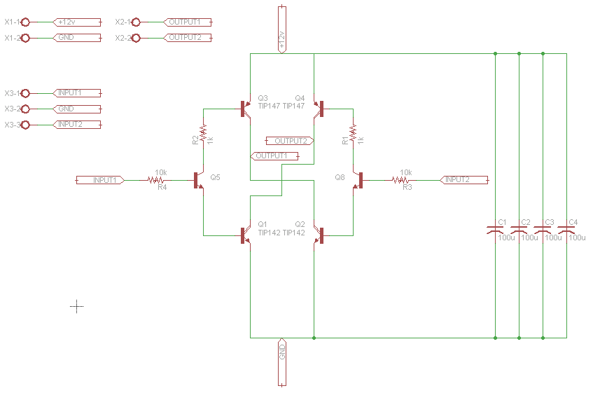
The 10A H-Bridge Motor Controller circuit looks simple but there are some key points that you don't want to miss. The main devices used in the circuit are the TIP147, TIP142 and 2n2222.
View Full Schematic
H-Bridge Schematic Specifics
Power Circuit
The power circuit is the +12v coming in from the terminal block X1-1/X1-2. It connects to a few 100uF capacitors and you might need more or less to help the motor run smoothly. The power also connects to the very top of the H-bridge (power to collector) and the very bottom (emitter to ground).
Motor Control Outputs
Outputs 1 and 2 are found in the middle of the H-bridge circuit, these connections feed into one of the dual terminal blocks, which connects to the DC motor. It is at these points of Output 1/2 where power will flow to drive the motor.
Digital Control Inputs
The triple terminal block X3-1/X3-2/X3-3 offer a way to connect up some digital circuitry and a ground to control the h-bridge. Input 1 controls one side of the H-bridge and Input 2 controls the other side.
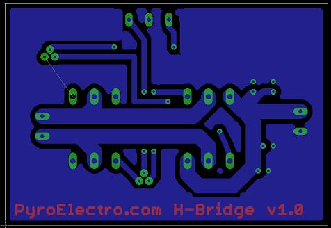
H-Bridge PC Board Layout Overview
View Full Board Layout
H-Bridge Board Layout Specifics
Thick vs. Thin Traces
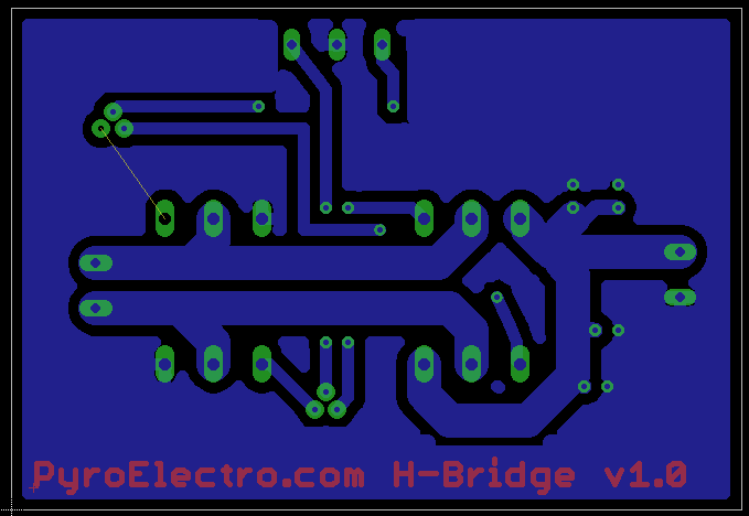
Typically when you have high very high currents going through a PCB you want two things: thick traces and proper heatsinks. You can see the thick traces on the board above going into the dual termianl block connecting to the DC motor. The thin traces are all digital connections.
Single Unrouted Trace
One yellow line still exists, and that is because it was a trace that would cut off a good ground connection to one of the power transistors. To fix this, a simple jumper wire will be used instead of a PCB trace.
Top vs. Bottom Layer
The bottom layer (in blue) is used purely for routing the signals to the proper devices. The top layer is used purely for the name of the board and for the top of the through-hole parts.
The 10A H-Bridge Motor Controller circuit looks simple but there are some key points that you don't want to miss. The main devices used in the circuit are the TIP147, TIP142 and 2n2222.
View Full Schematic
H-Bridge Schematic Specifics
Power Circuit
The power circuit is the +12v coming in from the terminal block X1-1/X1-2. It connects to a few 100uF capacitors and you might need more or less to help the motor run smoothly. The power also connects to the very top of the H-bridge (power to collector) and the very bottom (emitter to ground).
Motor Control Outputs
Outputs 1 and 2 are found in the middle of the H-bridge circuit, these connections feed into one of the dual terminal blocks, which connects to the DC motor. It is at these points of Output 1/2 where power will flow to drive the motor.
Digital Control Inputs
The triple terminal block X3-1/X3-2/X3-3 offer a way to connect up some digital circuitry and a ground to control the h-bridge. Input 1 controls one side of the H-bridge and Input 2 controls the other side.
H-Bridge PC Board Layout Overview
View Full Board Layout
H-Bridge Board Layout Specifics
Thick vs. Thin Traces
Typically when you have high very high currents going through a PCB you want two things: thick traces and proper heatsinks. You can see the thick traces on the board above going into the dual termianl block connecting to the DC motor. The thin traces are all digital connections.
Single Unrouted Trace
One yellow line still exists, and that is because it was a trace that would cut off a good ground connection to one of the power transistors. To fix this, a simple jumper wire will be used instead of a PCB trace.
Top vs. Bottom Layer
The bottom layer (in blue) is used purely for routing the signals to the proper devices. The top layer is used purely for the name of the board and for the top of the through-hole parts.