Project Info
Author: Chris
Difficulty: Medium
Time Invested: 2 Hours
Prerequisites:
Take a look at the above
articles before continuing
to read this article.
Author: Chris
Difficulty: Medium
Time Invested: 2 Hours
Prerequisites:
Take a look at the above
articles before continuing
to read this article.
Even though I have written many, other, motor control articles, none of them used a CPLD or FPGA as the main controller. This article will focus on explaining how to use a CPLD to take input from one device and then output appropriate signals to a motor controller IC, that will give us precise control over the DC motor's speed and direction.
Purpose & Overview Of This Project
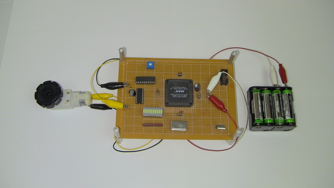
The goal of this project is to build a simple one input, one output system that will control a motor. The control input will come from a trimpot and the FPGA or CPLD's job will be to use the input to create the proper duty cycle PWM output to the DC motor controller.
To achieve this result, we will us a MAX150 analog-to-digital converter to capture the trimpot analog input, the same one as we used in the CPLD and ADC's tutorial. After the analog input is digitized the CPLD (EPM7128) will create standard PWM signals and output them to the SN755410NE DC motor controller IC. We will use the VHDL programming language for the CPLD in this project.