An Overview Of The FPGA DC Motor Control
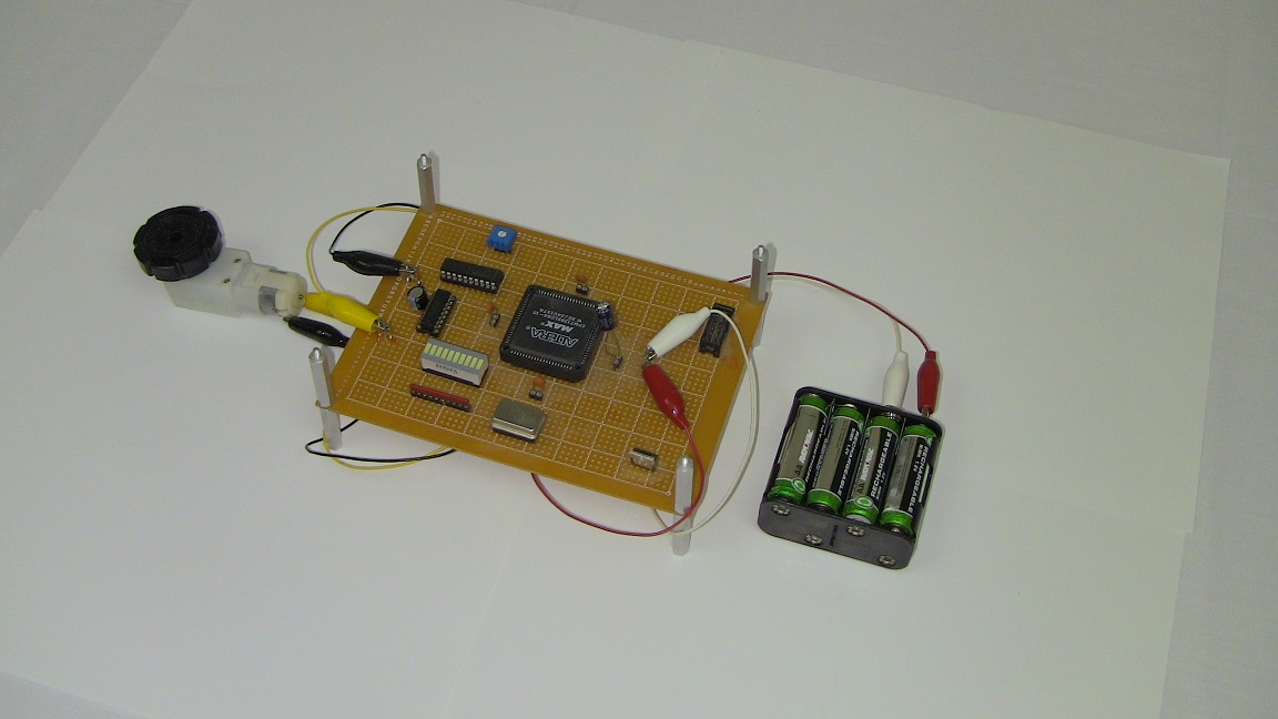
DC motor control is a first step for anyone looking to build their first robot. It's a stepping stone to greater things, and being able to do it with an FPGA or CPLD opens many doors to exact timing through custom digital circuits. Many high speed robotics found in manufacturing are controlled by FPGAs and not processors! Through this project I hope you have learned more about motor control, PWM and A-to-D converters and most importantly how they can be combined to create a motor control system.

What To Do Now
If you have the hardware ready to go, I would say jump forward and try controlling a small robot or robotic chassis with the motor control system we built in this project. Or you can test using other ADC devices for input or other more powerful motor controllers for larger motors, or simply build your own 10 Amp H-Bridge. Whatever route you take with this information, be sure to have fun!
Conclusion
The information presented in this article has been seen before but never with a CPLD or FPGA. The uniqueness brought to the table by the FPGA world is that you can create all your own control hardware through the programming language of VHDL or Verilog. Unlike software, the CPLD and FPGA allows you to build hardware modules that operate concurrently offering perfect timing to control motors, LEDs or anything that requires precise timing. The system explained in this article did just that and was successful. All the goals outlined in the purpose of this article have been reached, so let's say hurray, we were successful again!
If you have any further questions, I implore you...don't be shy, take a look at the forums or ask a question there. I check them out regularly and love getting comments & questions.
DC motor control is a first step for anyone looking to build their first robot. It's a stepping stone to greater things, and being able to do it with an FPGA or CPLD opens many doors to exact timing through custom digital circuits. Many high speed robotics found in manufacturing are controlled by FPGAs and not processors! Through this project I hope you have learned more about motor control, PWM and A-to-D converters and most importantly how they can be combined to create a motor control system.
What To Do Now
If you have the hardware ready to go, I would say jump forward and try controlling a small robot or robotic chassis with the motor control system we built in this project. Or you can test using other ADC devices for input or other more powerful motor controllers for larger motors, or simply build your own 10 Amp H-Bridge. Whatever route you take with this information, be sure to have fun!
Conclusion
The information presented in this article has been seen before but never with a CPLD or FPGA. The uniqueness brought to the table by the FPGA world is that you can create all your own control hardware through the programming language of VHDL or Verilog. Unlike software, the CPLD and FPGA allows you to build hardware modules that operate concurrently offering perfect timing to control motors, LEDs or anything that requires precise timing. The system explained in this article did just that and was successful. All the goals outlined in the purpose of this article have been reached, so let's say hurray, we were successful again!
If you have any further questions, I implore you...don't be shy, take a look at the forums or ask a question there. I check them out regularly and love getting comments & questions.