Hardware Design (Continued)
The resistor array & 7 segment LED display are added.
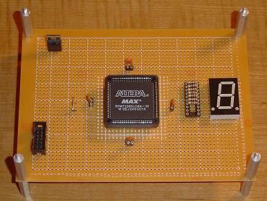
The green wires show where the LED stuff is wired up.
The board is now officially all wired up according to the schematic and ready to go. The next step is to program it and test it out. Granted we are extremely limited at what we can do with only a few simple device on the board, more peripherals can always easily be added.
With that in mind, the next step is the software side of things. Using Quartus II a sample program/design is created to make sure the 7-segment LED display lights up.
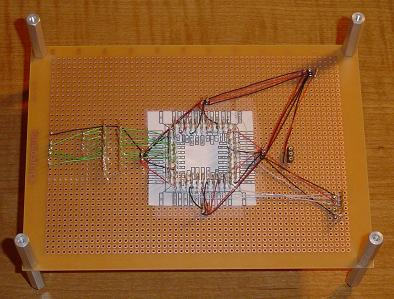
The resistor array & 7 segment LED display are added.
The green wires show where the LED stuff is wired up.
The board is now officially all wired up according to the schematic and ready to go. The next step is to program it and test it out. Granted we are extremely limited at what we can do with only a few simple device on the board, more peripherals can always easily be added.
With that in mind, the next step is the software side of things. Using Quartus II a sample program/design is created to make sure the 7-segment LED display lights up.