Hardware Design
Now we'll wire together the parts for the development board. Take a another look at the schematic and get going!
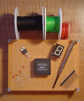
Here's a few of the parts that are needed to get started:
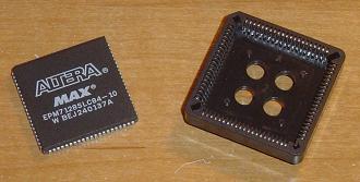
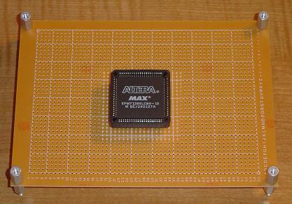
First we start with the CPLD and the PLCC socket. Securely place the CPLD into the PLCC Socket.
Now line the PLCC socket with SIPS so that it can be put into the proto board.
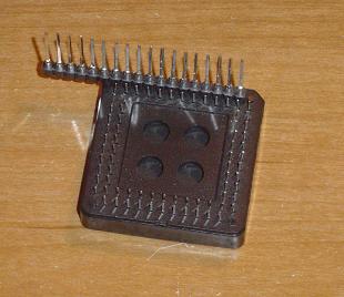
You can see how the SIPS will make wirewrapping far easier.
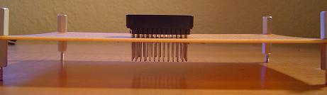
It's best to put the CPLD in the middle of the board.
Add four 2 pin SIPS with a 0.1uF Capacitior in it around the CPLD.
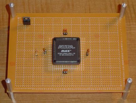
Now start wiring the basic power circuit from the 7805 to 2 SIP capacitors.
Afterward wire from the 2 SIP capacitors to the VCC & GND pins on the board.
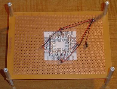
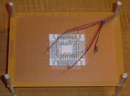
Next we'll wire the JTAG socket so that the PLD can be programmed using the ByteBlaster MV.
Now we'll wire together the parts for the development board. Take a another look at the schematic and get going!
Here's a few of the parts that are needed to get started:
First we start with the CPLD and the PLCC socket. Securely place the CPLD into the PLCC Socket.
Now line the PLCC socket with SIPS so that it can be put into the proto board.
You can see how the SIPS will make wirewrapping far easier.
It's best to put the CPLD in the middle of the board.
Add four 2 pin SIPS with a 0.1uF Capacitior in it around the CPLD.
Now start wiring the basic power circuit from the 7805 to 2 SIP capacitors.
Afterward wire from the 2 SIP capacitors to the VCC & GND pins on the board.
Next we'll wire the JTAG socket so that the PLD can be programmed using the ByteBlaster MV.