Hardware Design (Continued)
The best spot to add the JTAG socket at, is near the edge of the board.
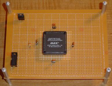
Only 7 wires come off of the JTAG socket; 4 to the CPLD and 3 to VCC & GND.
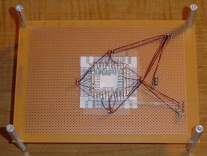
At this point the board created has the capability of being programmed. So if power and ground were to be hooked up and the ByteBlaster cable connected, Quartus II would see the device and program it without any issues.
Before we do that, let's add a small peripheral device, the 7-segment LED display. This way we can know for sure if the device is working by seeing the display light up.
The best spot to add the JTAG socket at, is near the edge of the board.
Only 7 wires come off of the JTAG socket; 4 to the CPLD and 3 to VCC & GND.
At this point the board created has the capability of being programmed. So if power and ground were to be hooked up and the ByteBlaster cable connected, Quartus II would see the device and program it without any issues.
Before we do that, let's add a small peripheral device, the 7-segment LED display. This way we can know for sure if the device is working by seeing the display light up.