Data & Observations
If everything was done correctly, right after it finishes programming and gets to 100% it should reset the CPLD and run the new configuration. If not, try reseting the device by taking power off and putting it back on.
The new configuration/program on the CPLD makes the 7-segment LED display do this:
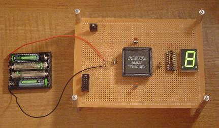
Perhaps not the most motivating or coolest thing ever, however with a working development board like this one, it is very easy to move on to do awesome things.
Programming Methods
Another observation I would like to make is that the program for this tutorial used the 'schematic design' method. There also exist VHDL & Verilog. These two 'things' are forms of Hardware Description Langauges (HDL). They are written programming languages that do the same thing as the schematic editor but allow for much, much more custimizability & inginuity.
VHDL & Verilog
The schematic design method for programming is great for beginners however VHDL and Verilog let you do the same thing often quicker and with more flexibility. The next tutorials with this board will be exploring these two programming langauges. The trickiest part of them is that they are concurrent languages. This means that several processes inside the CPLD/FPGA can be happening at the same time. This is something that a standard processor could never achieve.
If everything was done correctly, right after it finishes programming and gets to 100% it should reset the CPLD and run the new configuration. If not, try reseting the device by taking power off and putting it back on.
The new configuration/program on the CPLD makes the 7-segment LED display do this:
Perhaps not the most motivating or coolest thing ever, however with a working development board like this one, it is very easy to move on to do awesome things.
Programming Methods
Another observation I would like to make is that the program for this tutorial used the 'schematic design' method. There also exist VHDL & Verilog. These two 'things' are forms of Hardware Description Langauges (HDL). They are written programming languages that do the same thing as the schematic editor but allow for much, much more custimizability & inginuity.
VHDL & Verilog
The schematic design method for programming is great for beginners however VHDL and Verilog let you do the same thing often quicker and with more flexibility. The next tutorials with this board will be exploring these two programming langauges. The trickiest part of them is that they are concurrent languages. This means that several processes inside the CPLD/FPGA can be happening at the same time. This is something that a standard processor could never achieve.