Hardware Design
Before we can get to the actual circuit, we're going to need to build 2 specialized connectors. The schematic clearly shows which pins are used on the DB25 parallel port and 10 pin JTAG connectors so let's built up these two connectors with some wire wrap, solder and ribbon cable.
Building The JTAG Connector
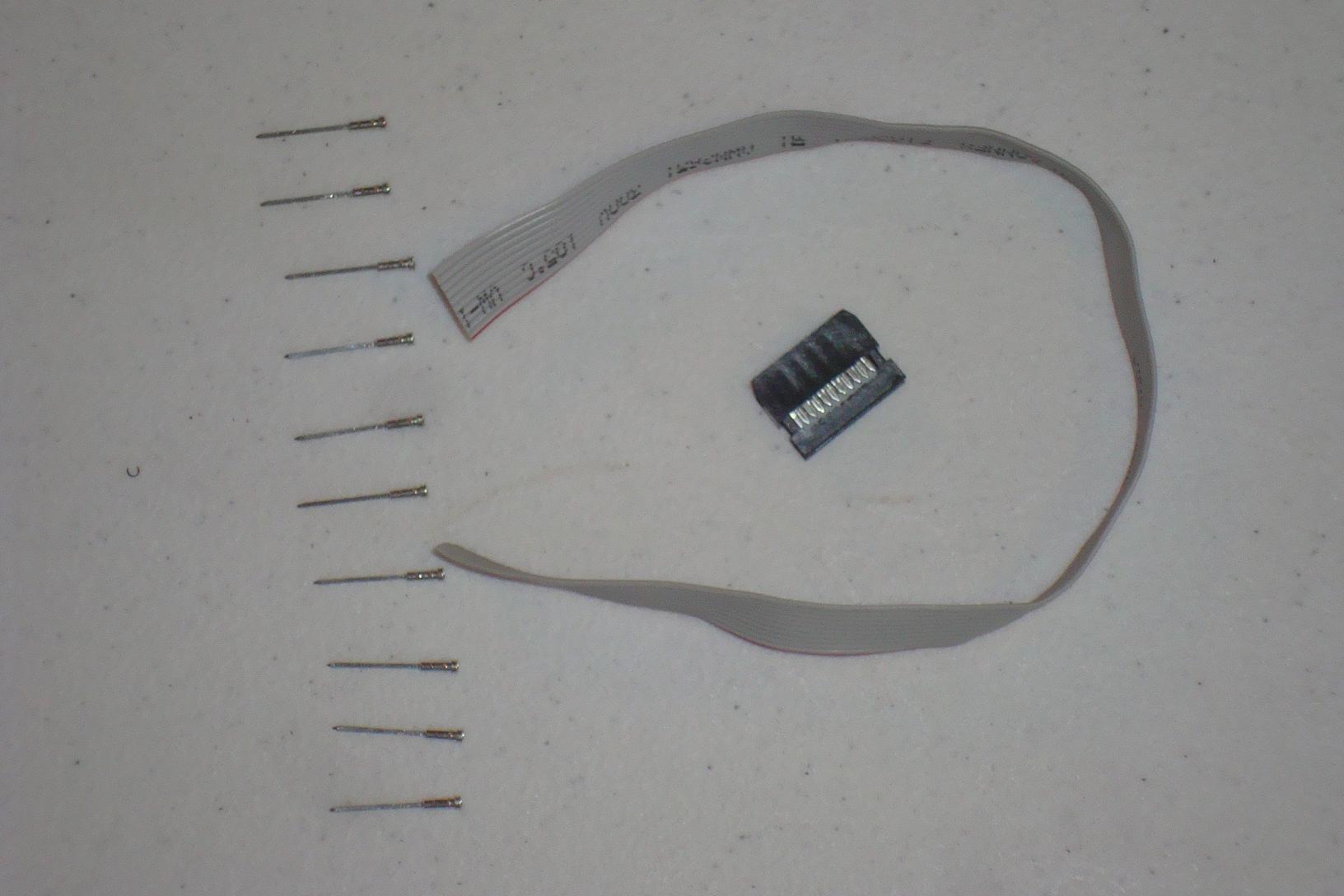
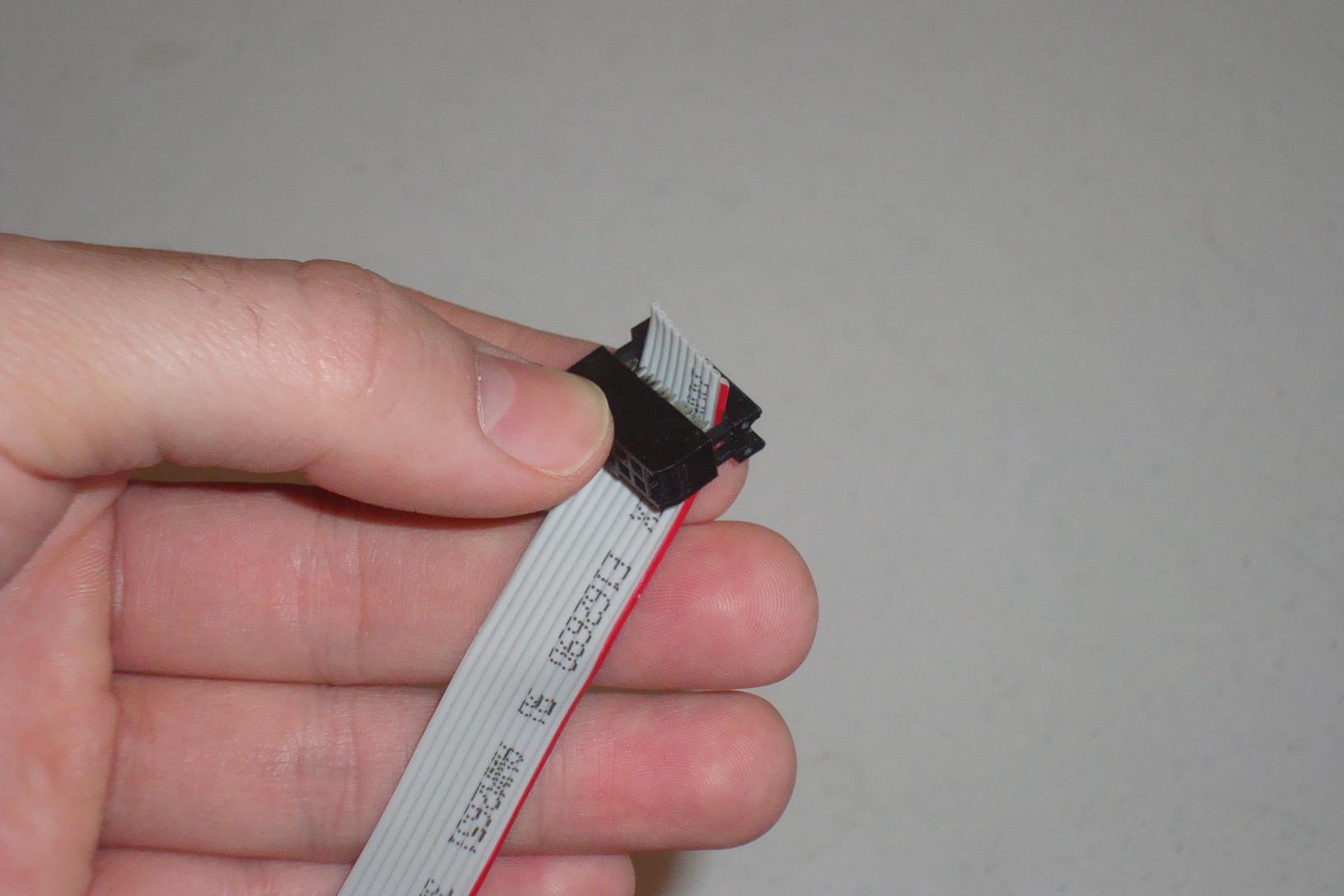
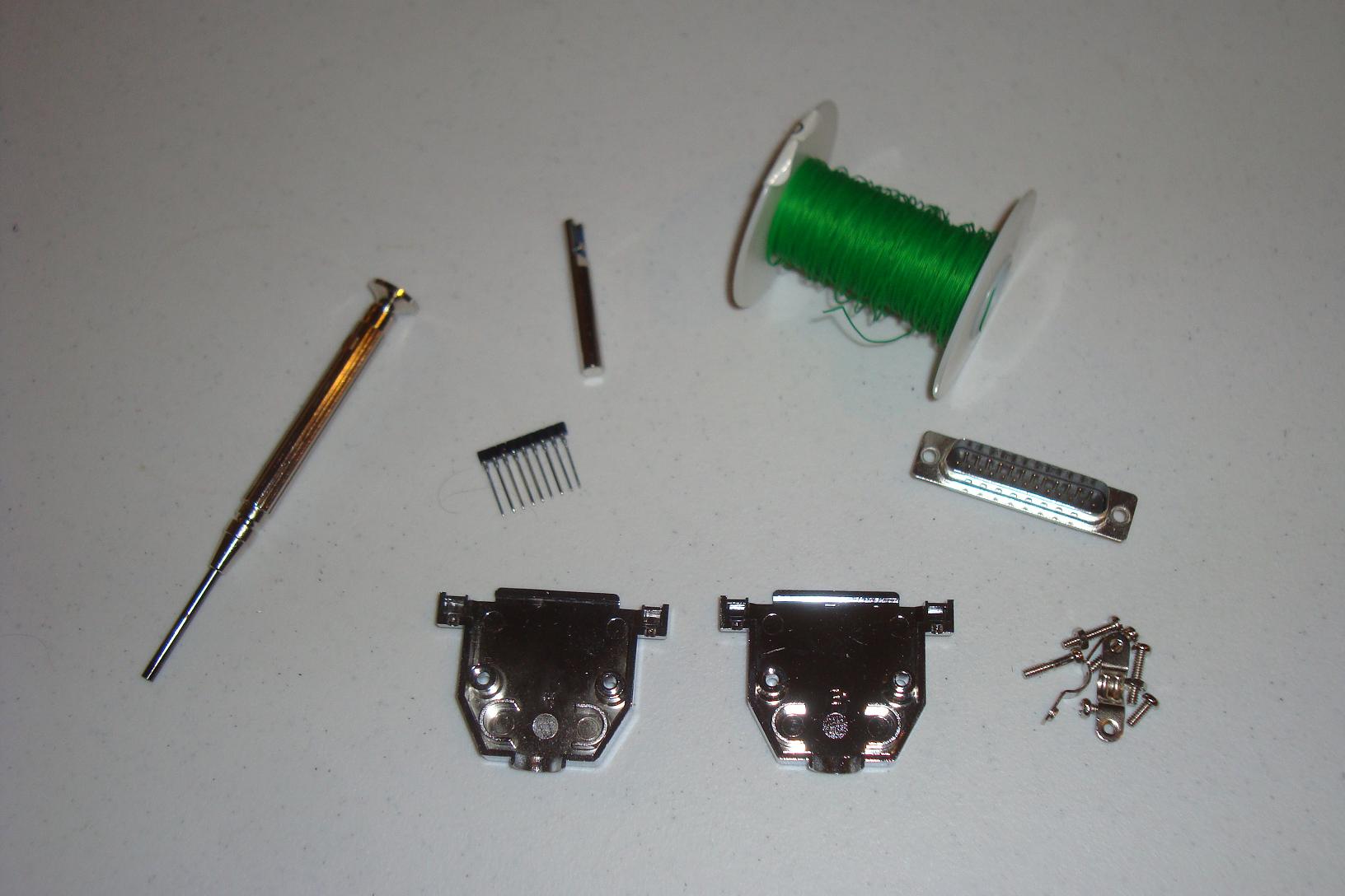
The JTAG connector requires minimal parts.
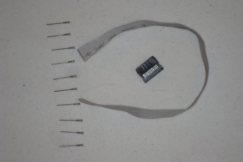
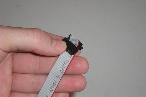
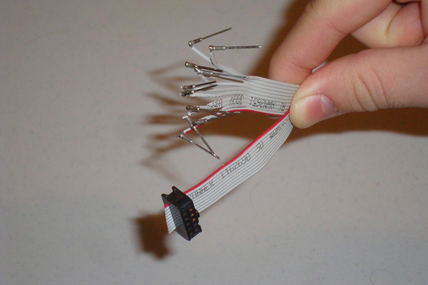
·The ribbon cable goes through the open space in the connector. Then you press the connector back together and all the connections are made in the connector!
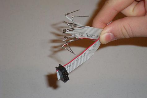
·Next, each of the 10 wires from the ribbon cable is soldered to a SIP so that it can be easily connected to a breadboard.
Building The DB25 Parallel Port Connector
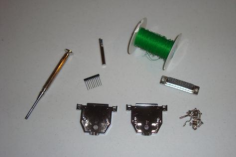
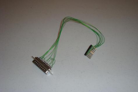
The DB25 Connector will require substantial more work and soldering. I use small wire wrap wire to make all the connections onto the DB25 connector.
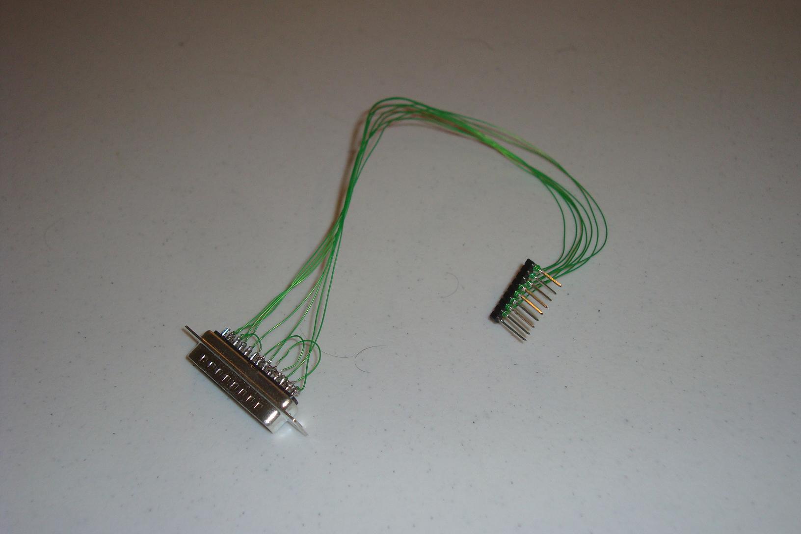
·Below you can see the soldered connections from the parallel port connector, ready to be wire wrapped to some SIPs.
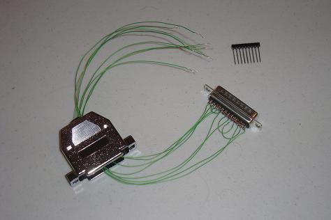
·Next, Each of the DB25 connections is wire wrapped onto the SIPs, which will connect nicely into the breadboard.
·Now we are ready to build the actual circuit!
Before we can get to the actual circuit, we're going to need to build 2 specialized connectors. The schematic clearly shows which pins are used on the DB25 parallel port and 10 pin JTAG connectors so let's built up these two connectors with some wire wrap, solder and ribbon cable.
Building The JTAG Connector
The JTAG connector requires minimal parts.
·The ribbon cable goes through the open space in the connector. Then you press the connector back together and all the connections are made in the connector!
·Next, each of the 10 wires from the ribbon cable is soldered to a SIP so that it can be easily connected to a breadboard.
Building The DB25 Parallel Port Connector
The DB25 Connector will require substantial more work and soldering. I use small wire wrap wire to make all the connections onto the DB25 connector.
·Below you can see the soldered connections from the parallel port connector, ready to be wire wrapped to some SIPs.

·Next, Each of the DB25 connections is wire wrapped onto the SIPs, which will connect nicely into the breadboard.
·Now we are ready to build the actual circuit!