The Theory
The theory for how this motor control system works will be described in two parts. The first part describes the input signal called PWM short for Pulse with Modulation and the second will describe which pulses go where to control speed and direction.
PWM Explained - Pulse With Modulation
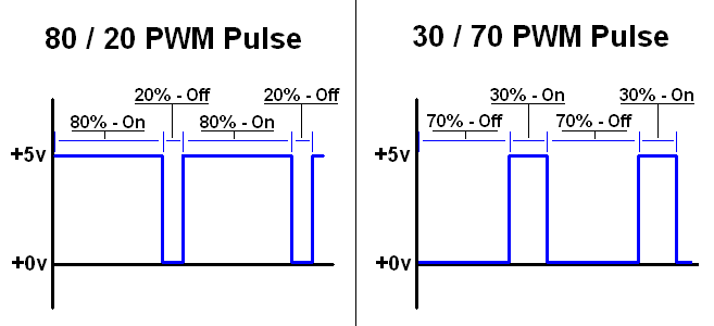
The two images above show you two different PWM signals. The first signal is "on" 80% of the time. That means it is at +5v for 80% of the period of the signal. This is a powerful signal and if input into the SN754410, would make a motor spin very fast -- forward. The second image shows you a signal similar to the first, but it is only on 30% of the time. It is at +0v for 70% of the period of the signal. Since this PWM signal is in an 'off' state for the majority of the time, this will actually make the SN754410 tell the motor to spin in reverse at a medium speed. The center point, 50%/50% tells the motors to stay idle with no movement.
SN754410 PWM Input
Looking at one side of the SN754410, we have a motor connected to 1Y and 2Y. A PWM signal that is 80% on // 20% off is input into 1A and the differential signal to 2A. The corresponding output to the motor makes it turn very fast (almost full speed) in the clockwise direction.

If we look at the same setup but change the input PWM to 20% on // 80% off , the motor will spin counter-clockwise (reverse) rather at roughly the same speed as the previous example. The motor spins in the opposite direction because the current is being input on the other side of the motor (pin 2A), thusly it flows the opposite direction through the motor compared to the first example.
The theory for how this motor control system works will be described in two parts. The first part describes the input signal called PWM short for Pulse with Modulation and the second will describe which pulses go where to control speed and direction.
The two images above show you two different PWM signals. The first signal is "on" 80% of the time. That means it is at +5v for 80% of the period of the signal. This is a powerful signal and if input into the SN754410, would make a motor spin very fast -- forward. The second image shows you a signal similar to the first, but it is only on 30% of the time. It is at +0v for 70% of the period of the signal. Since this PWM signal is in an 'off' state for the majority of the time, this will actually make the SN754410 tell the motor to spin in reverse at a medium speed. The center point, 50%/50% tells the motors to stay idle with no movement.
Looking at one side of the SN754410, we have a motor connected to 1Y and 2Y. A PWM signal that is 80% on // 20% off is input into 1A and the differential signal to 2A. The corresponding output to the motor makes it turn very fast (almost full speed) in the clockwise direction.
If we look at the same setup but change the input PWM to 20% on // 80% off , the motor will spin counter-clockwise (reverse) rather at roughly the same speed as the previous example. The motor spins in the opposite direction because the current is being input on the other side of the motor (pin 2A), thusly it flows the opposite direction through the motor compared to the first example.