Hardware Design
For this part of the project we will assemble the circuit seen in the schematic to the robot chassis from Part 1: The Chassis. The circuit assembly is a step by step process that I took photos of so that you could easily follow along. So let's get started!
Building The Circuit
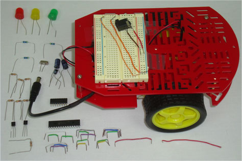
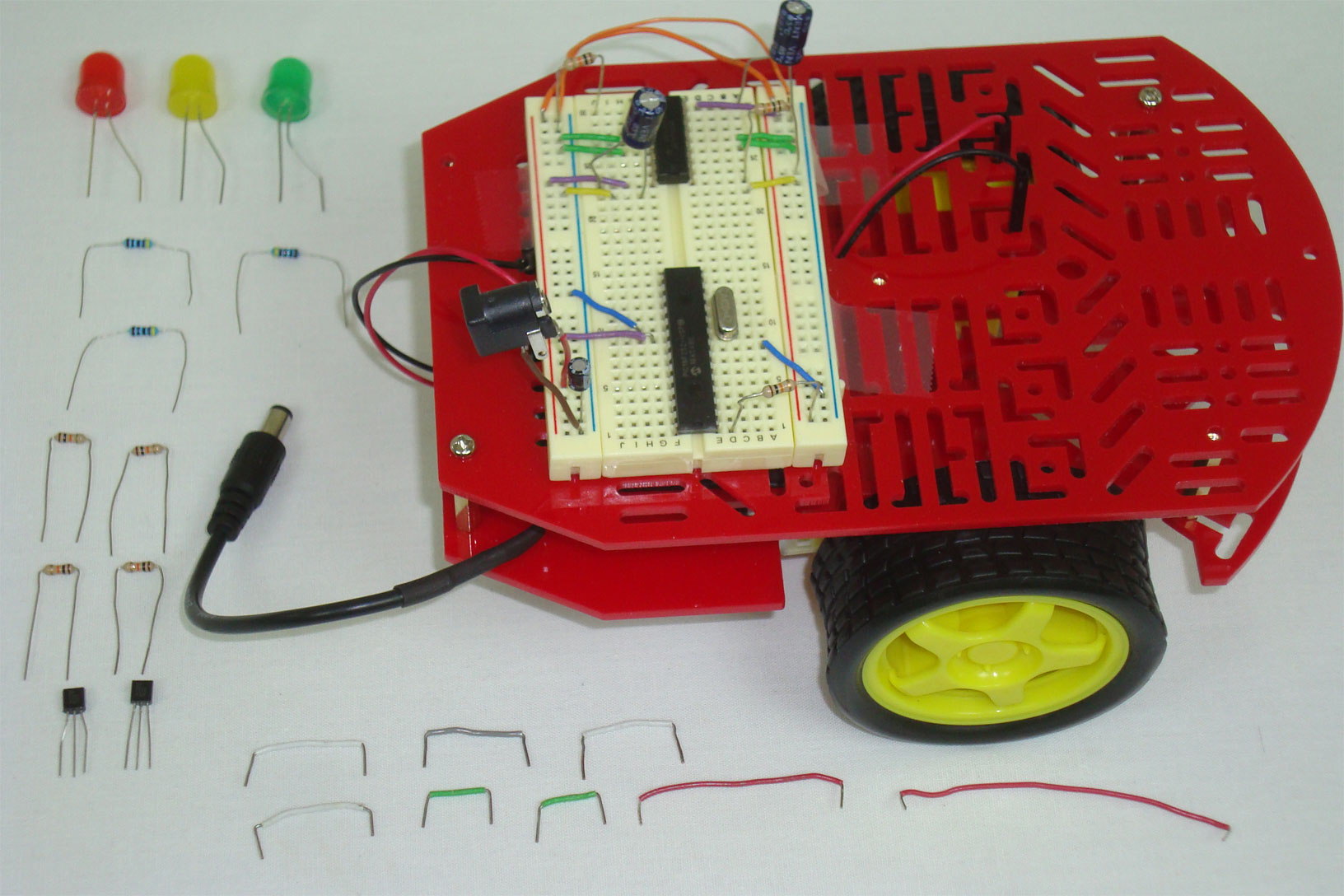
· Below you can see all of the parts used in this circuit laid out on a table.
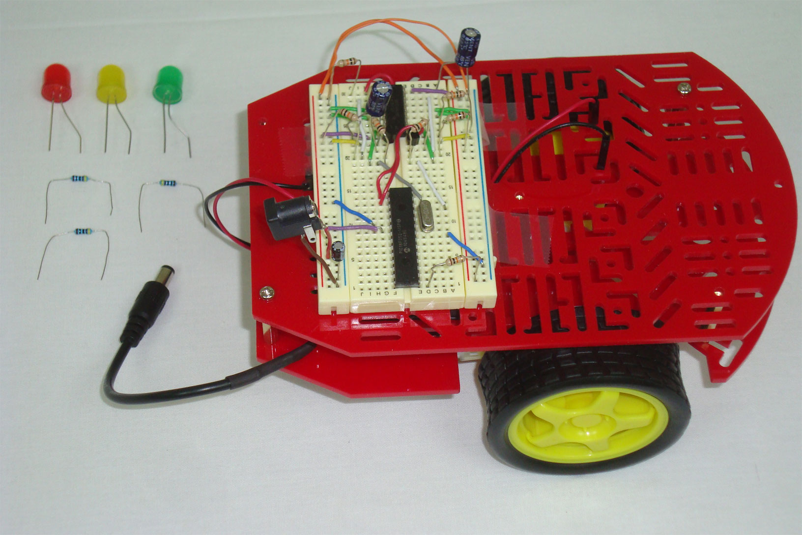
·All the power supply connections to the breadboard are made.
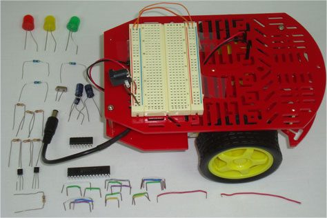
·The basic PIC 18F252 circuit is assembled.
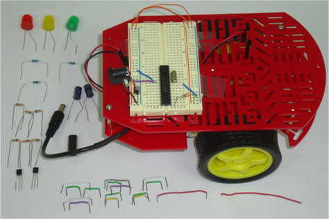
·The motor controller circuit is assembled at the other end of the breadboard.

·The PWM Inversion circuit is built to connect the PIC to Motor Controller.
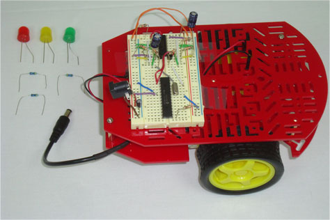
·The last step is connecting the 3 Output LEDs to the breadboard.

·The circuit is complete, now we need to program the PIC with firmware.
For this part of the project we will assemble the circuit seen in the schematic to the robot chassis from Part 1: The Chassis. The circuit assembly is a step by step process that I took photos of so that you could easily follow along. So let's get started!
Building The Circuit
· Below you can see all of the parts used in this circuit laid out on a table.

·All the power supply connections to the breadboard are made.

·The basic PIC 18F252 circuit is assembled.

·The motor controller circuit is assembled at the other end of the breadboard.
·The PWM Inversion circuit is built to connect the PIC to Motor Controller.
·The last step is connecting the 3 Output LEDs to the breadboard.
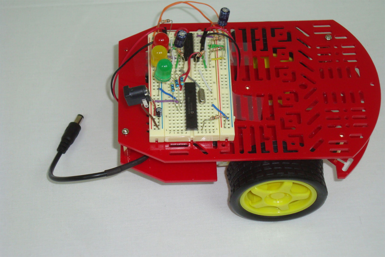
·The circuit is complete, now we need to program the PIC with firmware.