Schematic Overview
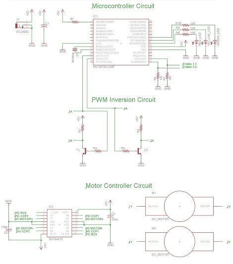
The schematic for controlling the motors is split up into three main parts, with each part having a unique functionality. The main parts used and seen in the schematic below are the 18F252, SN754410 and 2N2222 Transistors.
View Full Schematic
Schematic Specifics
Microcontroller Circuit
Seen at the very top, the microcontroller circuit consists of the PIC 18F252, its 40 MHz crystal, a few LEDs, the enable lines going to the motor controller and the PWM signals going to the PWM inversion circuit and the motor controller.
PWM Inversion Circuit
Two transistors (2n2222) are used to invert the two PWM signals that are travelling to the motor controller. This is done because the motor controller needs to have both the 'positive' PWM signal and the 'negative' PWM signal in what is called a differential pair. The motor controller cannot control our DC motors without both the positive and negative PWM signals.
Motor Control Circuit
The main part used for the motor control circuit is the SN754410. This is a quadrule half h-bridge motor controller IC. To use this motor controller, you must input a differential PWM signal, provide power and ground and enable the bank to start-up your motors. The control signals that will tell the motor controller to do all this will be sent from the PIC.
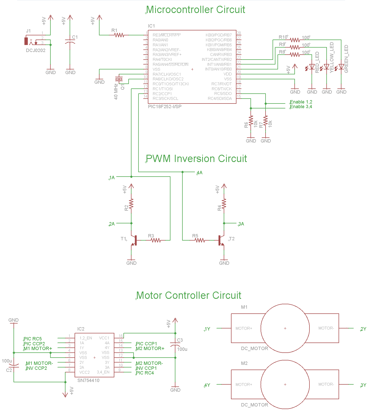