Animatronic Mouth Servo Hardware Design
The majority of what needs to be built for this project is mechanical, because the electronic side was built in previous tutorials eyebrows/eyes. This section will show you step by step how the animatronic mouth was built and then what modifications were made to the electronics to add 1 more servo port.
Building The Circuit
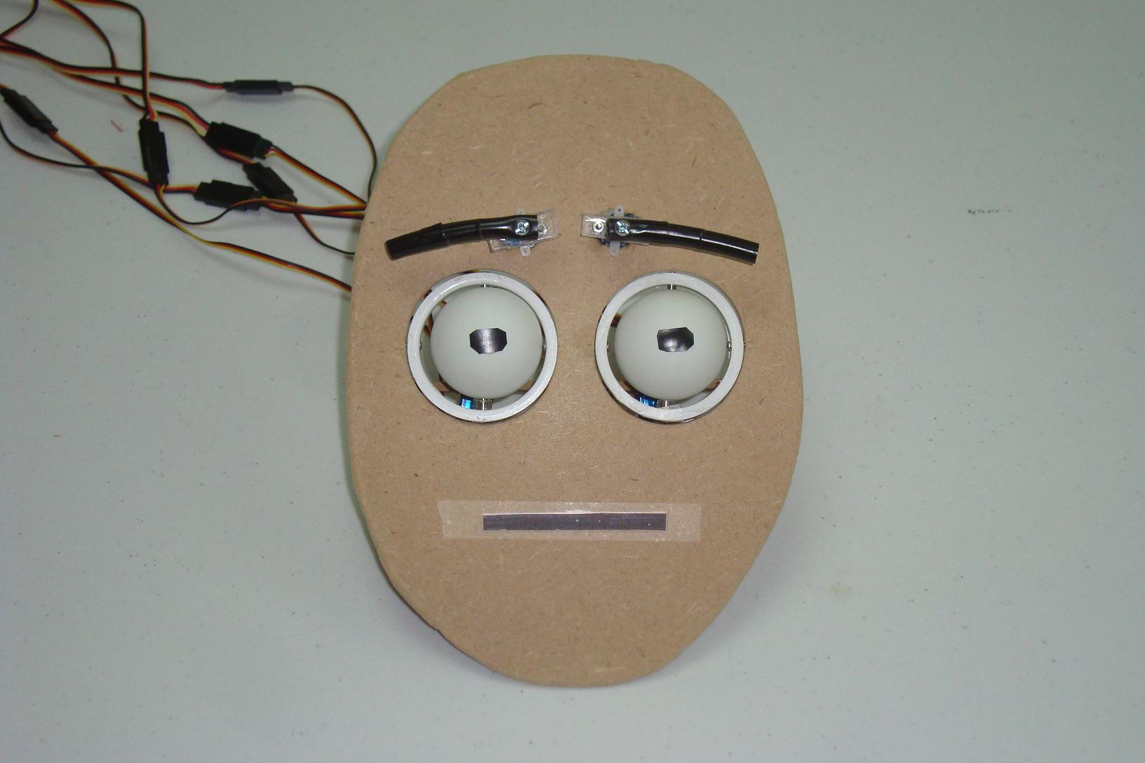
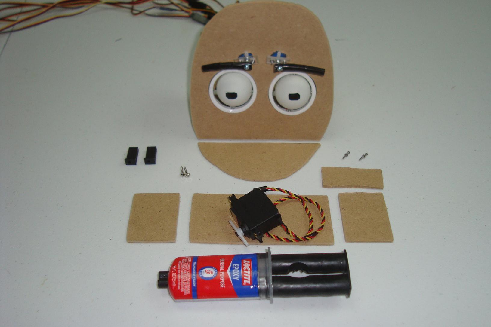
The first steps of adding the animatronic mouth were to cut off the existing mouth and modify the face.

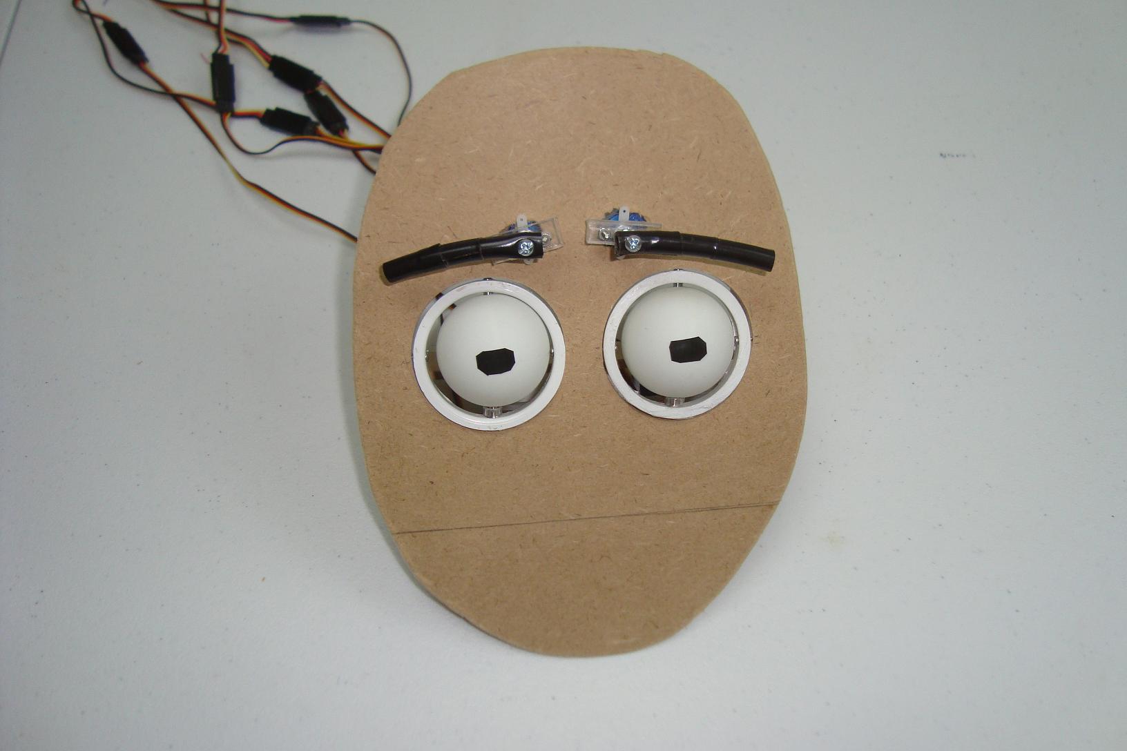
·Peel off the lips that were taped on as a place holder.

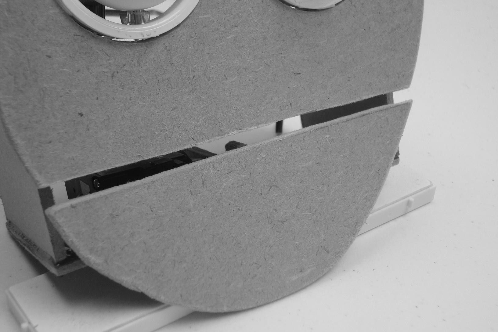
·Cut the mouth off with a perfect line.

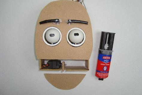
·Gather the other parts, screws, MDF and epoxy.

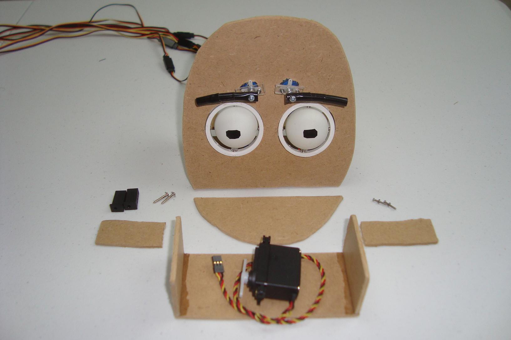
·First a support is made to hold the mouth servo.

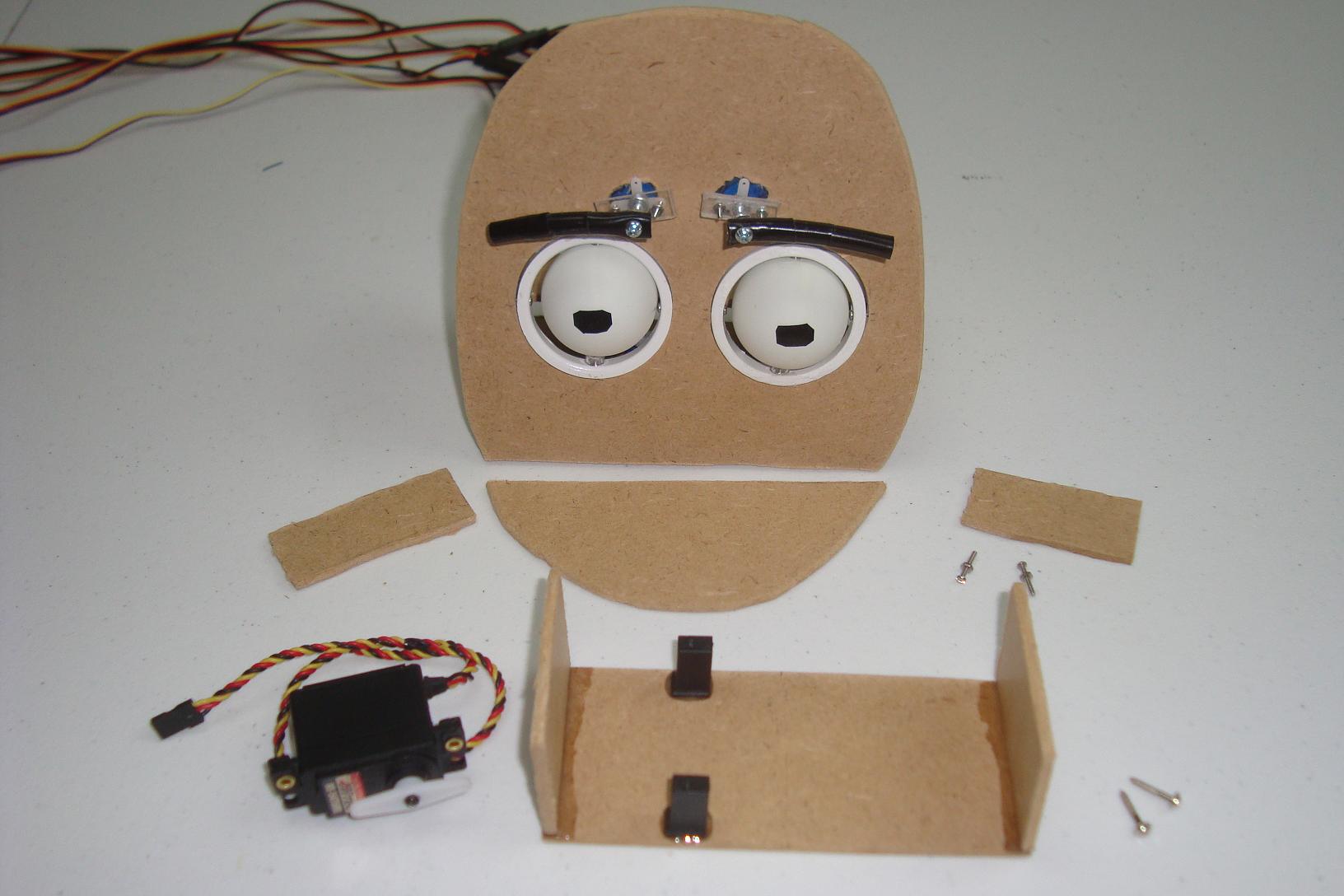
·The two servo mounts are e-poxy'd to the MDF.

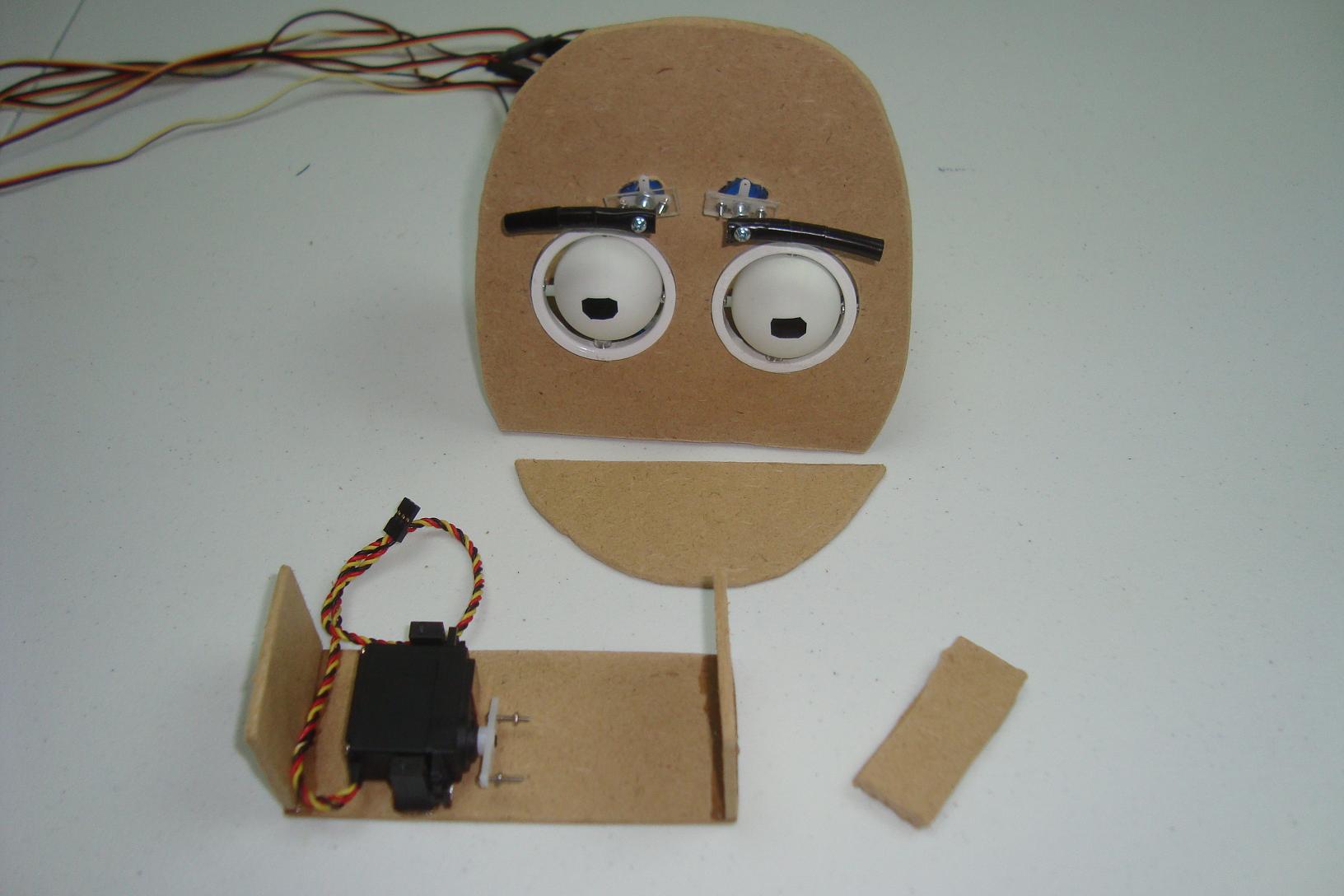
·The servo is screwed to the mount.

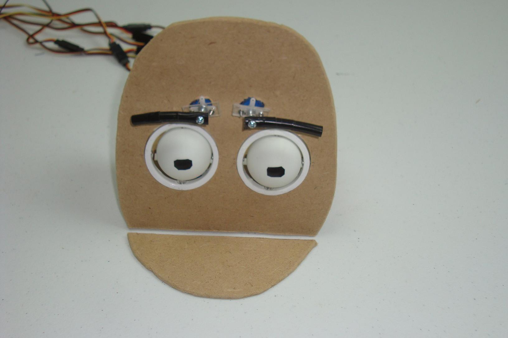
·The mount is e-poxy'd to the rest of the face.

·The MDF connector from servo to mouth is attached.
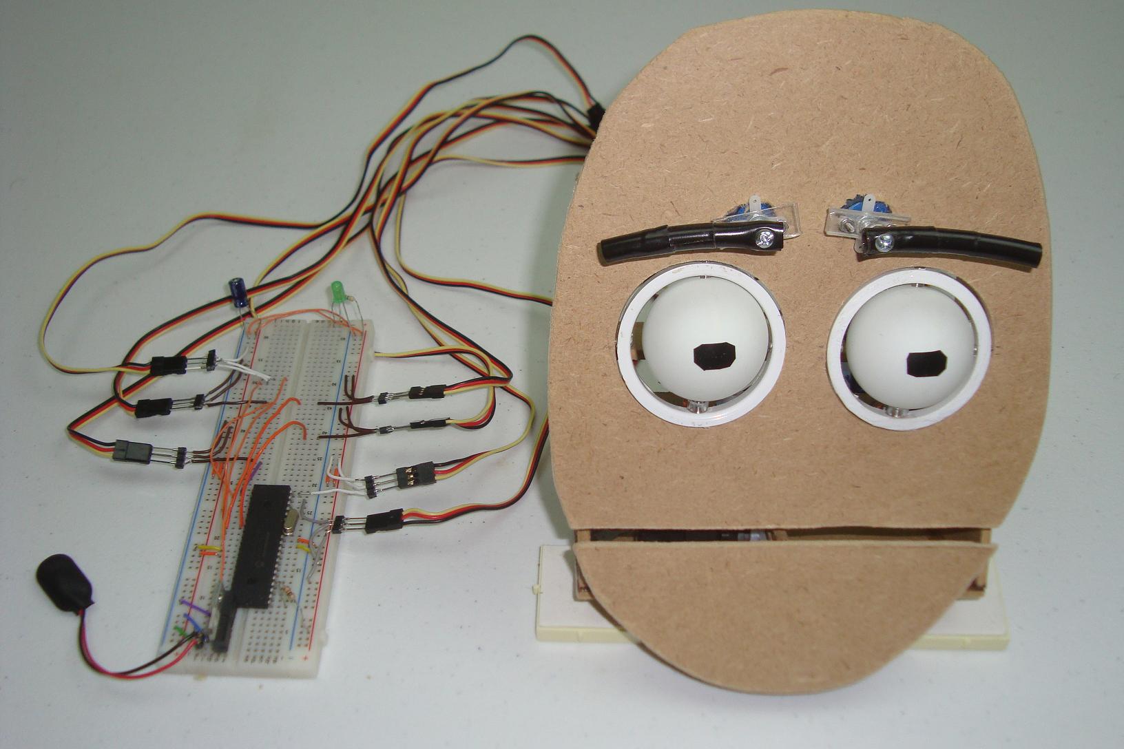
·After the final E-poxy, the mouth is firmly on the face.

·The final step, is modifying the electronics.

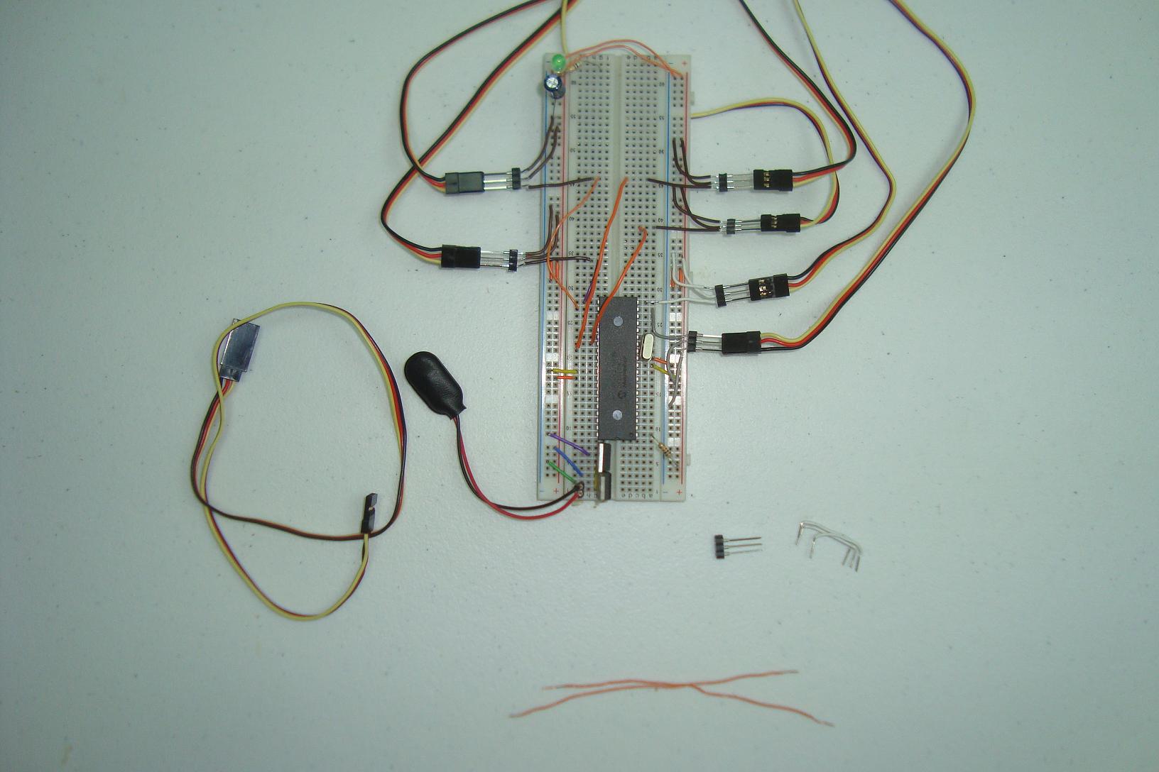
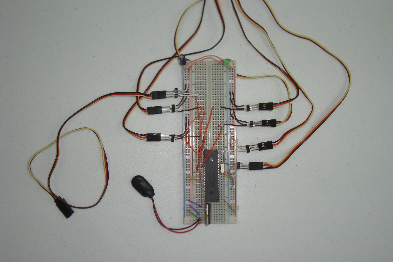
·First an extra 7805 power regulation circuit is added.

·Next the servo port is connected onto the breadboard.

·Electronics are done, get the software started!

·We'll take a quick look at the alternate LCD mouth design and then start looking at the software.
The majority of what needs to be built for this project is mechanical, because the electronic side was built in previous tutorials eyebrows/eyes. This section will show you step by step how the animatronic mouth was built and then what modifications were made to the electronics to add 1 more servo port.
Building The Circuit
The first steps of adding the animatronic mouth were to cut off the existing mouth and modify the face.
·Peel off the lips that were taped on as a place holder.
·Cut the mouth off with a perfect line.
·Gather the other parts, screws, MDF and epoxy.
·First a support is made to hold the mouth servo.
·The two servo mounts are e-poxy'd to the MDF.
·The servo is screwed to the mount.
·The mount is e-poxy'd to the rest of the face.

·The MDF connector from servo to mouth is attached.

·After the final E-poxy, the mouth is firmly on the face.
·The final step, is modifying the electronics.

·First an extra 7805 power regulation circuit is added.
·Next the servo port is connected onto the breadboard.
·Electronics are done, get the software started!
·We'll take a quick look at the alternate LCD mouth design and then start looking at the software.