Schematic Overview
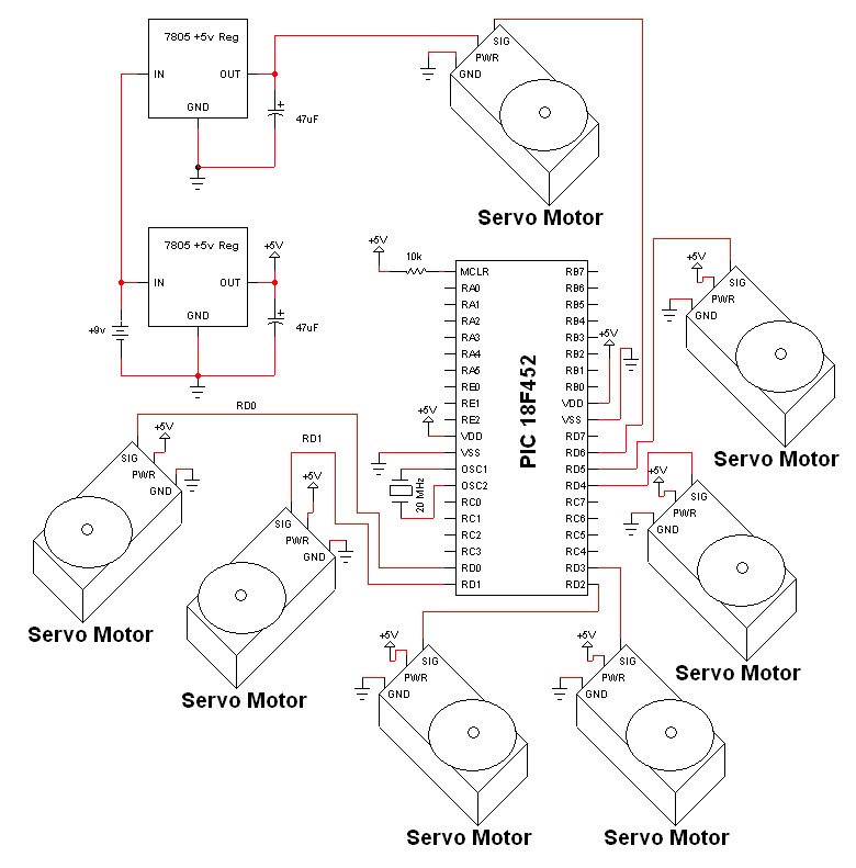
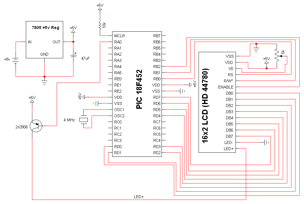
The electronic designs for the two animatronic mouths can be seen below. The first design is for the articulated mouth, the extra servos are for the eyebrows and eyes. The second design is for the LCD mouth. It is very similar to the custom characters on an LCD tutorial's schematic. The most important parts seen in these two electronic schematics are the HS-485HB Servo, 7805, PIC 18F452 and 16x2 LCD Display.
Animatronic Mouth Schematic

View Full Schematic
Animatronic Mouth Schematic Specifics
Power Circuit
The power supply circuit is seen in two places. One for powering the PIC and most of the small HS-55 servos for the eyes and eyebrows. The second place, is powering the newly added HS-485HB servo for articulating the mouth. This servo requires more power from the regulator, so the easiest option was to add a second regulator for safety.
Microcontroller Circuit
The 18F452 PIC's PORTD is used for controlling all of the servos. Each servo is driven by a specific pin on the PIC meaning we have independent control over every servo's movement at any given time.
Servo Motors
There are now a total of 7 servo motors used to actuate the movement seen in this animatronic face. 2 servos are used for the eyebrows, 4 servos for the two eyes and now one servo will be used to move the animatronic mouth up and down.
LCD Mouth Schematic

View Full Schematic
LCD Mouth Schematic Specifics
Power Circuit
The standard +5v regulator circuit seen in many of my tutorials and projects will be used to provide power to the LCD and the PIC. This regulator converts the battery's +12v down to +5v which our digital electronics require.
Microcontroller Circuit
To drive the LCD and control the backlight, a PIC 18F452 microcontroller will be used. This microcontroller is seen in many of my projects and is very easy to program for and to work with.
8-Bit LCD Interface
The interface to the LCD from the Microcontroller uses PORTD for passing Data, PORTB for control signals and PORTA for backlight control. This design requires more wiring in order to access the LCD's character arrays, however it could be reduced if we used the reduced 4-bit data bus option with the LCD.
The electronic designs for the two animatronic mouths can be seen below. The first design is for the articulated mouth, the extra servos are for the eyebrows and eyes. The second design is for the LCD mouth. It is very similar to the custom characters on an LCD tutorial's schematic. The most important parts seen in these two electronic schematics are the HS-485HB Servo, 7805, PIC 18F452 and 16x2 LCD Display.
View Full Schematic
Animatronic Mouth Schematic Specifics
Power Circuit
The power supply circuit is seen in two places. One for powering the PIC and most of the small HS-55 servos for the eyes and eyebrows. The second place, is powering the newly added HS-485HB servo for articulating the mouth. This servo requires more power from the regulator, so the easiest option was to add a second regulator for safety.
Microcontroller Circuit
The 18F452 PIC's PORTD is used for controlling all of the servos. Each servo is driven by a specific pin on the PIC meaning we have independent control over every servo's movement at any given time.
Servo Motors
There are now a total of 7 servo motors used to actuate the movement seen in this animatronic face. 2 servos are used for the eyebrows, 4 servos for the two eyes and now one servo will be used to move the animatronic mouth up and down.
View Full Schematic
LCD Mouth Schematic Specifics
Power Circuit
The standard +5v regulator circuit seen in many of my tutorials and projects will be used to provide power to the LCD and the PIC. This regulator converts the battery's +12v down to +5v which our digital electronics require.
Microcontroller Circuit
To drive the LCD and control the backlight, a PIC 18F452 microcontroller will be used. This microcontroller is seen in many of my projects and is very easy to program for and to work with.
8-Bit LCD Interface
The interface to the LCD from the Microcontroller uses PORTD for passing Data, PORTB for control signals and PORTA for backlight control. This design requires more wiring in order to access the LCD's character arrays, however it could be reduced if we used the reduced 4-bit data bus option with the LCD.