Schematic Overview
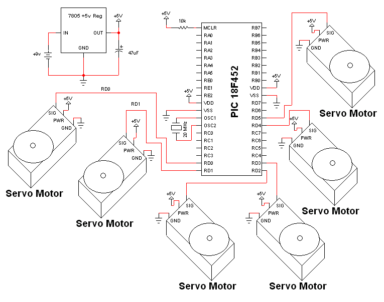
The electrical schematic for controlling the servo motors that we're using as acuators is surprisingly simple due to the fact that the servos are very self contained. The PIC will control them with a specific signal for each servo. The main devices used in the circuit are the Pico Servo or Sub-Micro Servos , 7805 and PIC 18F452.
View Full Schematic
Schematic Specifics
Power Circuit
The power regualtion circuit seen above is one that I use across most of my projects. The LM7805 +5v linear regulator will keep the output to our system. at a constant stream of +5v. The 47uF dc filtering cap will help keep the current flow steady and eliminate some noise.
Microcontroller Circuit
The PIC circuit consists of the 20 MHz crystal, some connections to power and ground and a 10kΩ resistor pulling pin 1 up to +5v. PORTD's RD0 and RD1 will be used to send control signals to the servo motors.
Servo Circuit
As I mentioned before, the servo motors are self contained in that they only require 3 things from us as designers. [1] Power (+4v-+6v preferred), [2] Ground and [3] a PWM input signal. Power and ground are very easy connections to make, the control PWM input signal is a little more difficult, but the PIC will take care of generating that.