Schematic Overview
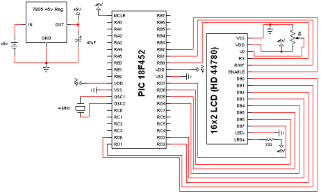
The schematic for this tutorial can be seen drawn out below. It includes everything you'd need to wire up for the tutorial to work. PIC programming circuitry is not included in the schematic as I'm assuming either you're programming the PIC out of circuit or can add the few elements into the circuit on your own for in-circuit programming.
View Full Schematic
Schematic Specifics
16x2 LCD Interface Circuit
The 16x2 LCD interface has 8 data bits (DB0~DB7) and 3 control pins (RS,R/W*,E). The data bits are connected to the 8 pins of PORTD on the PIC. A special note to take is that the LCD data pins match the PIC pin-numbers. The control lines are connected to the lower 3 bits of PORTB on the PIC.
Contrast Control
As mentioned in the parts list, the 5k trimpot will control the contrast for the LCD. The schematic above shows you how the trimpot should be connected to the LCD, Power and Ground. After it is connected when you turn the trimpot dial characters on the screen will appear lighter and darker.
The Backlight LED
Most 16x2 LCD's have a backlight LED unless you opted to save a few bucks. There's nothing special about these two pins (15 and 16). Slap a resistor infront of anode and connect the cathode to ground and immediately the backlight should turn on.
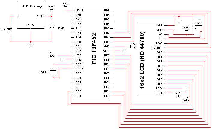