Hardware Design
The hardware design for this project is just to follow the schematic we saw a few pages ago. Luckily there aren't too many connections that need to be made, just double check with your multimeter (continuity tester) that everything is wired up and touching. I already wire-wrapped my setup together, so I'll show a few pictures of the assembled setup I'm using.
Building The Circuit
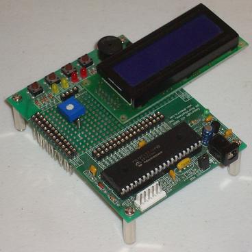
·Here you can see the development board and 16x2 LCD from the top.
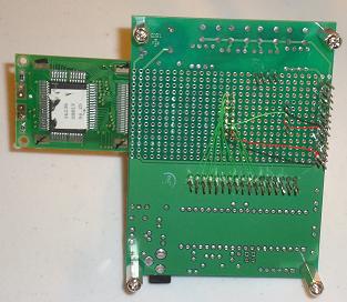
·The development board & wire-wrap connections from below.
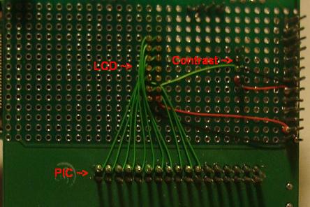
·A close-up picture of the LCD wire-wrap connections.
Again, nothing special was done here, I followed the schematic and wire-wrapped the pins on the LCD to the PIC, as well as to the trimpot for contrast and to power and ground.
The hardware design for this project is just to follow the schematic we saw a few pages ago. Luckily there aren't too many connections that need to be made, just double check with your multimeter (continuity tester) that everything is wired up and touching. I already wire-wrapped my setup together, so I'll show a few pictures of the assembled setup I'm using.
Building The Circuit
·Here you can see the development board and 16x2 LCD from the top.

·The development board & wire-wrap connections from below.
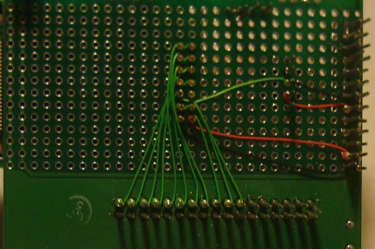
·A close-up picture of the LCD wire-wrap connections.
Again, nothing special was done here, I followed the schematic and wire-wrapped the pins on the LCD to the PIC, as well as to the trimpot for contrast and to power and ground.