Project Info
Author: Chris
Difficulty: Medium-Difficult
Time Invested: 9 Hours
Prerequisites:
Take a look at the above
tutorials before continuing
to read this tutorial.
Author: Chris
Difficulty: Medium-Difficult
Time Invested: 9 Hours
Prerequisites:
Take a look at the above
tutorials before continuing
to read this tutorial.
The accelerometer is an interesting sensor that is now extremely tiny thanks to MEMS technology. Specifically, the accelerometer senses gravity, and since earth has a constant 1 g-force always pulling toward the center, we can use that reference to find the tilt of any object. With some digital design and LEDs added to the mix we can even build a tilt sensor as I will show you in this article.
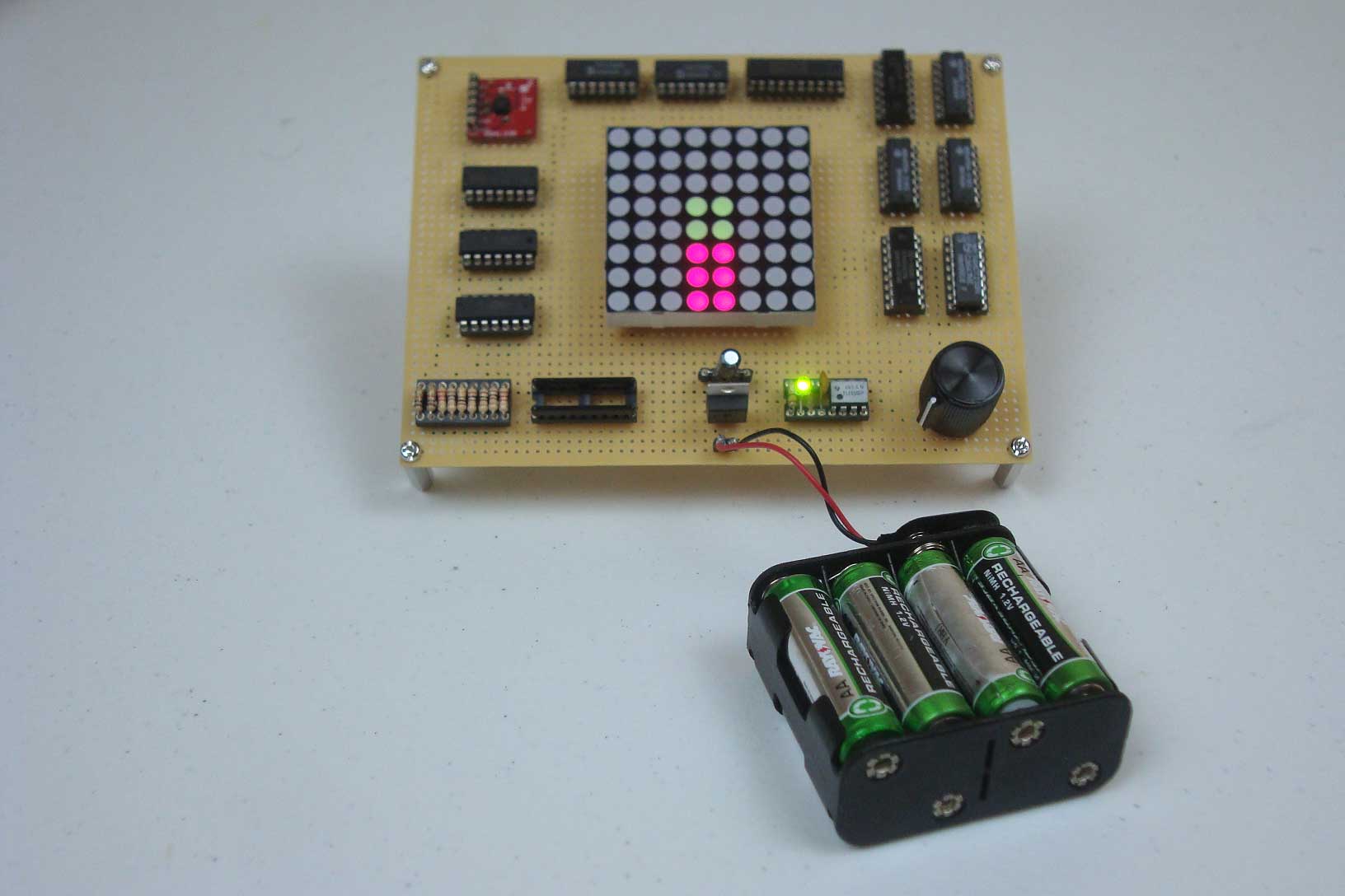
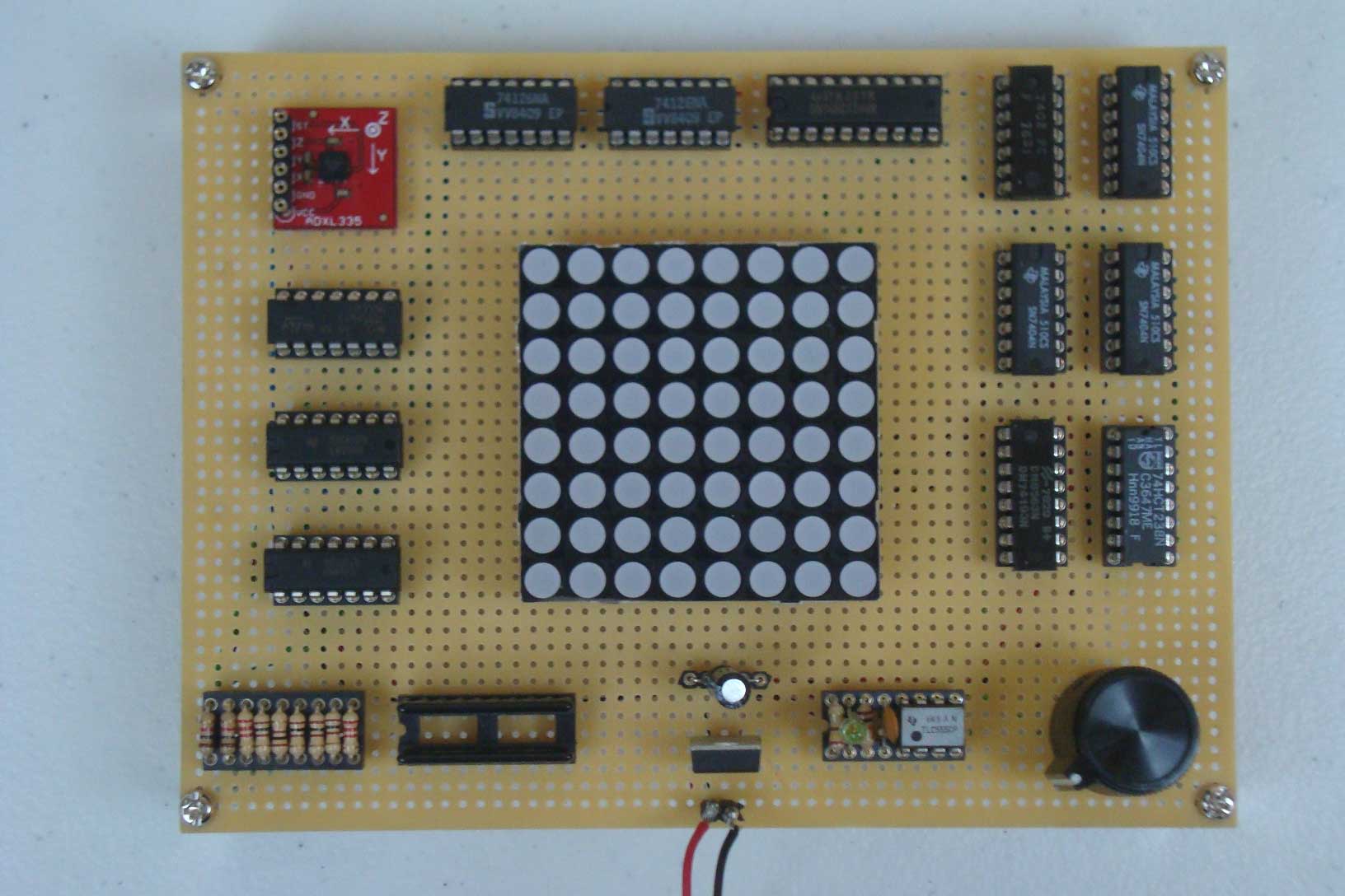
Purpose & Overview of this project
The purpose of this project is to build a working tilt sensor. The tilt sensor should have 3 core components:
- [1] A Custom Comparator Based Analog to Digtal Converter
- [2] An 8-State Machine To Drive The LED Matrix
- [3] Logic Buffers To Connect The A/D To The LED Matrix Display
The custom analog to digital converter should use a multiple resistor voltage divider for reference voltages. It should be designed in a way so that the reference voltages reflect various 'degrees' of tilt from the accelerometer's analog output. The 8-state machine should use a 555 timer, a 74-193 binary counter and a 74-238 de-multplexer. The state outputs should be used as enables signals into the LED driving logic buffers. This will allow the LED matrix to reflect the current tilt magnitude based off of the a-to-d output.