Assembling The RF Receiver PCB
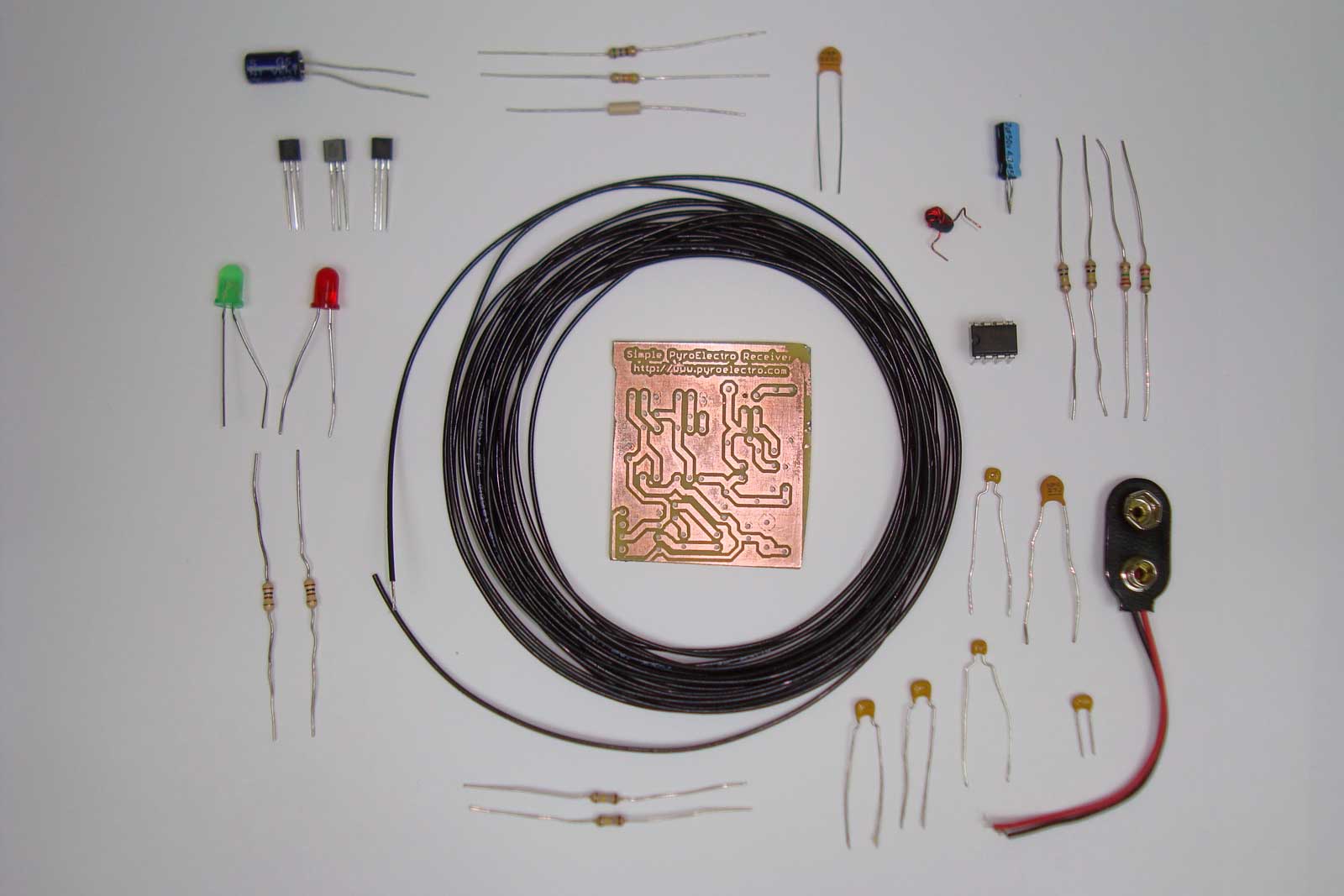
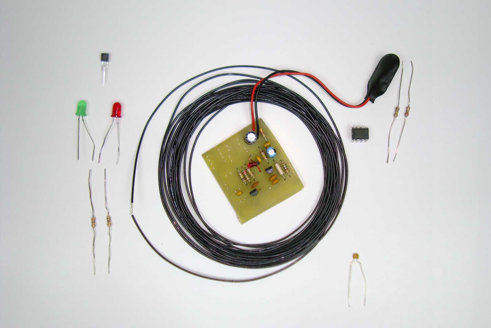
Below you can see all the parts necessary to get started wiring the circuit up exactly as you saw in the schematic details. First we start by gathering all the parts we need and the PCB:
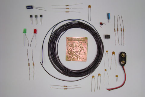
·My first assembly step was building the receiver front-end.
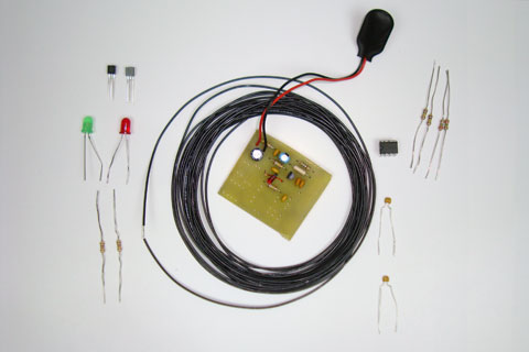
·Next the first amplifier stage is added.
·Finally, the Hsync and Vsync connections are made so that the monitor can catch what resolution an timing you want to display to it.
·And then the second amplifier stage.
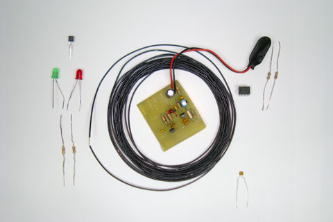
·Finally, the 555 timer receiver/LED driver circuit is soldered into place.
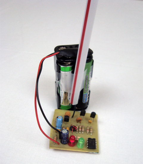
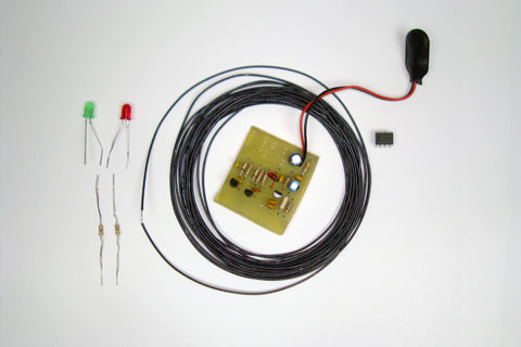
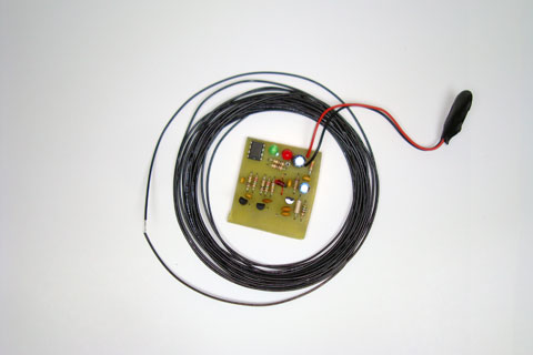
·To build the antenna just attach a wire to the PCB. The longer the better, but 12-18" is good enough. I used some straws to keep the antenna straight as you can see above. Now, the moment is here, let's test this stuff out!
Below you can see all the parts necessary to get started wiring the circuit up exactly as you saw in the schematic details. First we start by gathering all the parts we need and the PCB:
·My first assembly step was building the receiver front-end.
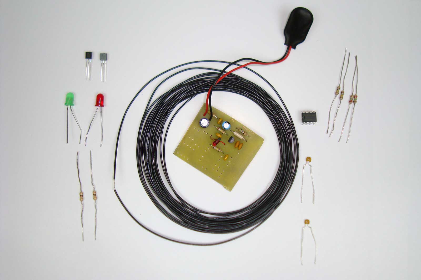
·Next the first amplifier stage is added.
·Finally, the Hsync and Vsync connections are made so that the monitor can catch what resolution an timing you want to display to it.
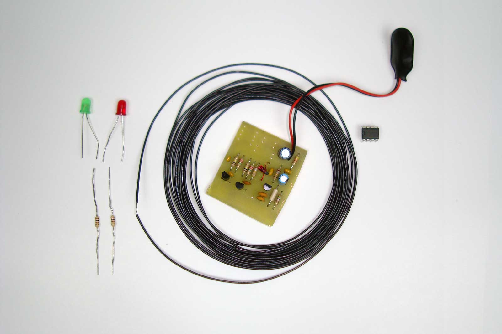
·And then the second amplifier stage.
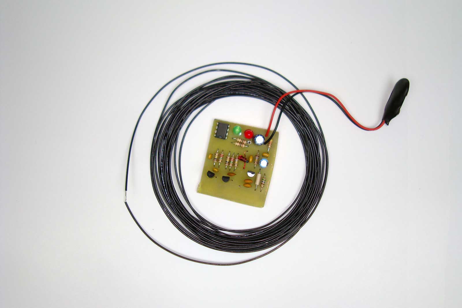
·Finally, the 555 timer receiver/LED driver circuit is soldered into place.
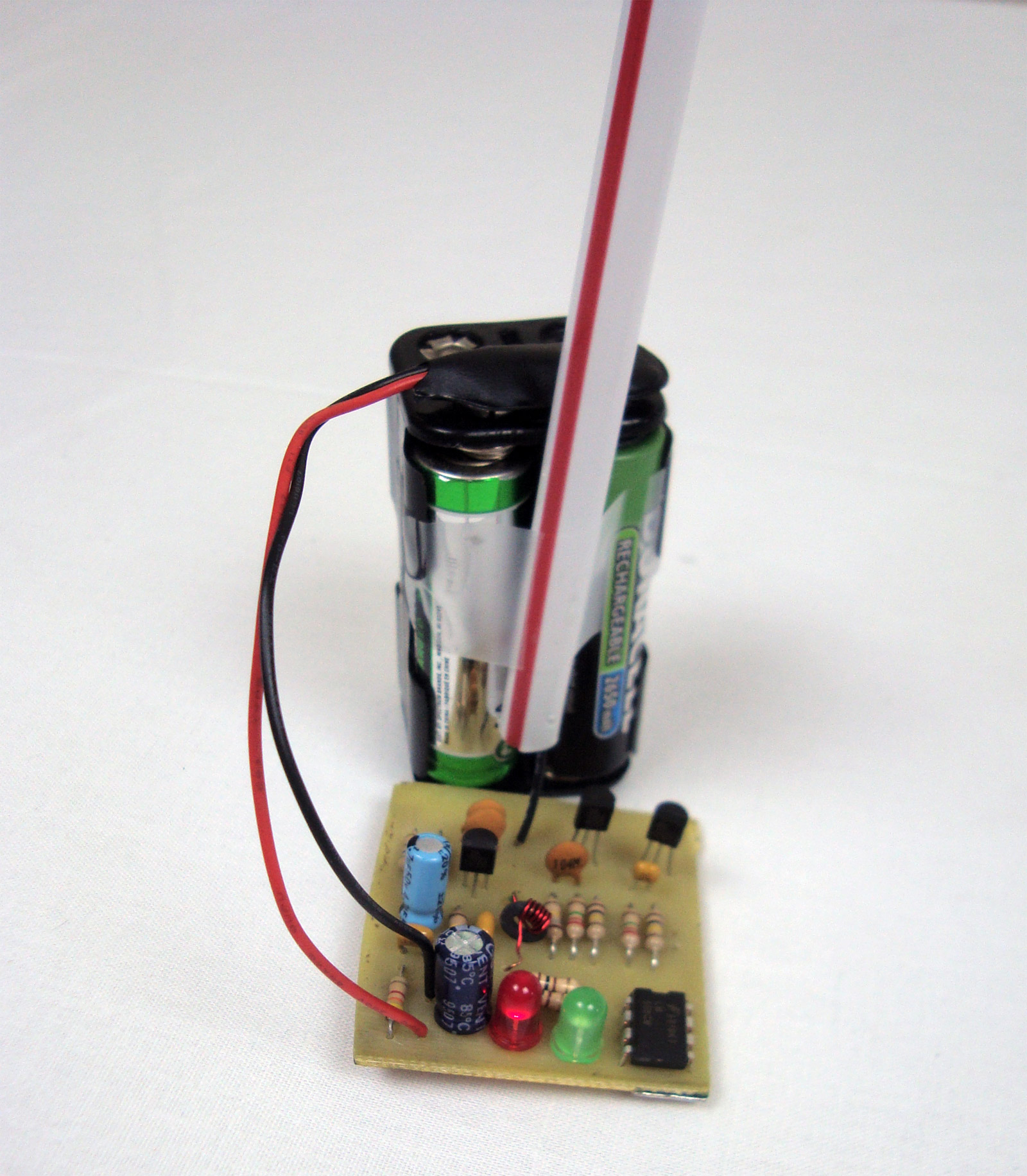
·To build the antenna just attach a wire to the PCB. The longer the better, but 12-18" is good enough. I used some straws to keep the antenna straight as you can see above. Now, the moment is here, let's test this stuff out!