Electrical Hardware Design
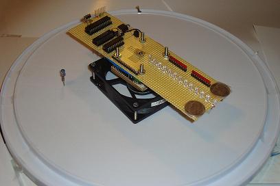
Strictly speaking, you just need to follow the schematic for this portion of the build process. Part placement can make the system vibrate a lot so either [a] try to balance the weight on both sides of the proto-board (you'll see later I added two coins) or [b] place the parts as close to the middle of the protoboard as possible.
Building The Circuit
Just like before, get all of the electrical parts together and let's get started soldering and wire-wrapping. As a side note: I had only seen PCB POV designs across the web and so for my design I thought I would prove to the world that an old-school wire-wrapped POV would work just as well.

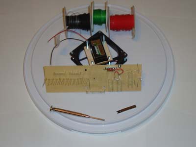
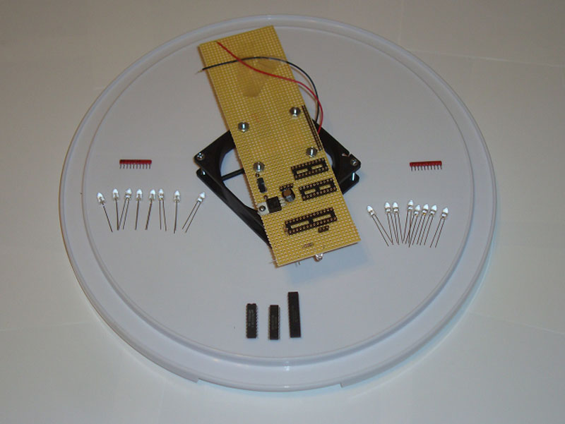
·First place all of the Wire-Wrap sockets, Power Circuity and SIPs down.
·Next place the LEDs on the opposite side and as close together as possible. The closer they are, the better that output numbers or text will look.
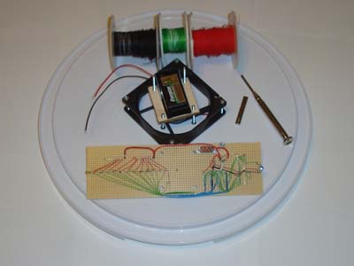
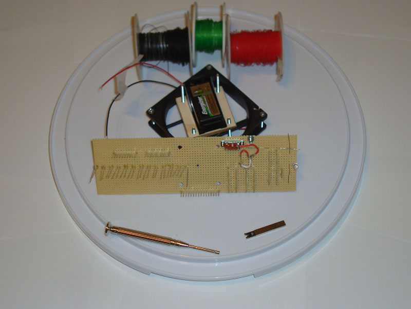
·Now comes the time-consuming part of wire wrapping The parts together.
·First I wire wrapped the control circuitry of the PIC and Latches.

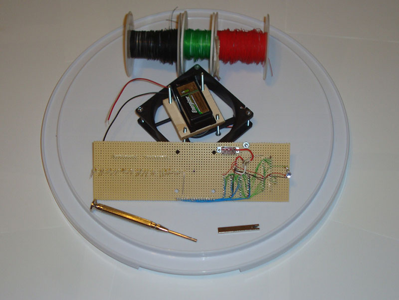
·Then I wire wrapped the LEDs up to power and the control circuitry.
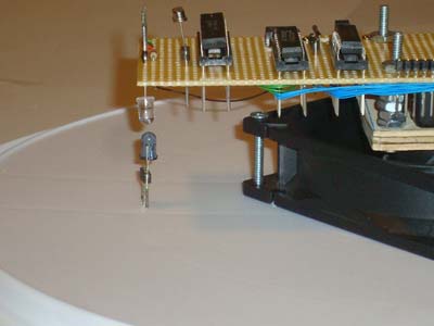
·The last step is adding the IR emitter diode to the base.
·This IR diode should be attached firmly to the base......

·....and located directly under the Phototransistor on the protoboard.
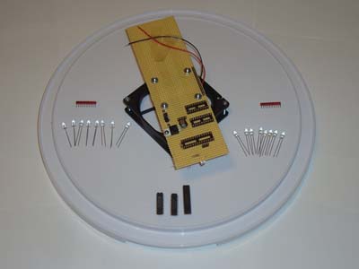
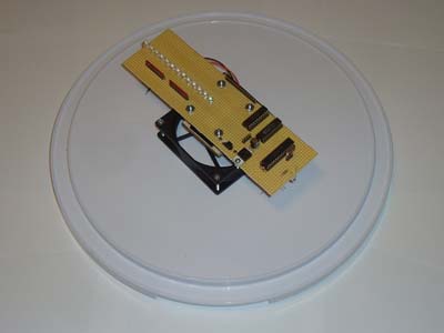
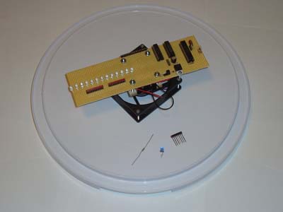
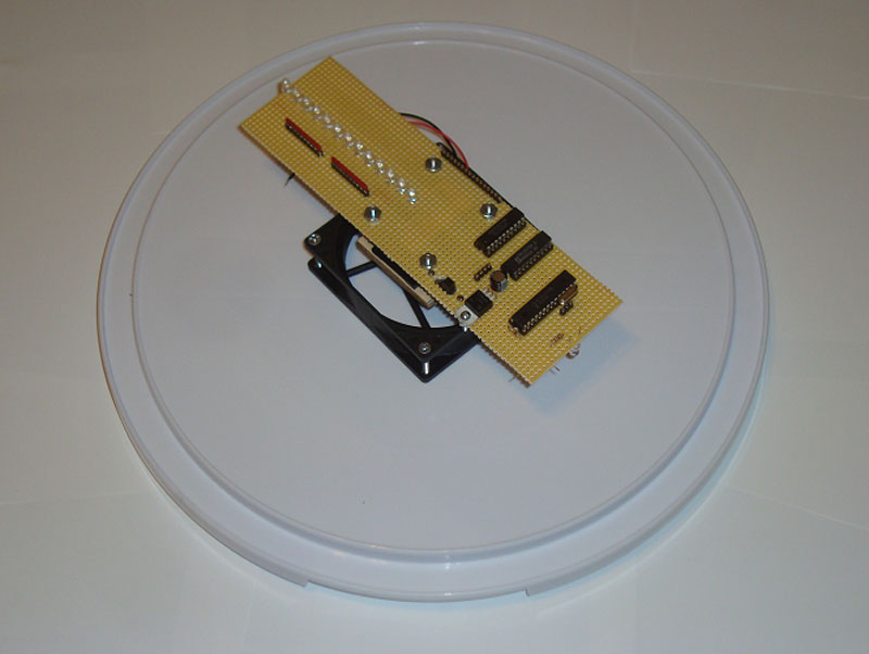
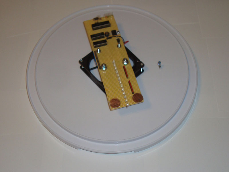
·The build process is now complete. Here is the POV:
·With the POV completed, Let's load some software onto it and test it out!
Strictly speaking, you just need to follow the schematic for this portion of the build process. Part placement can make the system vibrate a lot so either [a] try to balance the weight on both sides of the proto-board (you'll see later I added two coins) or [b] place the parts as close to the middle of the protoboard as possible.
Building The Circuit
Just like before, get all of the electrical parts together and let's get started soldering and wire-wrapping. As a side note: I had only seen PCB POV designs across the web and so for my design I thought I would prove to the world that an old-school wire-wrapped POV would work just as well.
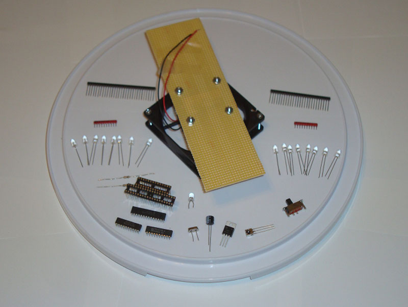
·First place all of the Wire-Wrap sockets, Power Circuity and SIPs down.
·Next place the LEDs on the opposite side and as close together as possible. The closer they are, the better that output numbers or text will look.
·Now comes the time-consuming part of wire wrapping The parts together.
·First I wire wrapped the control circuitry of the PIC and Latches.
·Then I wire wrapped the LEDs up to power and the control circuitry.

·The last step is adding the IR emitter diode to the base.

·This IR diode should be attached firmly to the base......
·....and located directly under the Phototransistor on the protoboard.

·The build process is now complete. Here is the POV:

·With the POV completed, Let's load some software onto it and test it out!