Schematic Overview
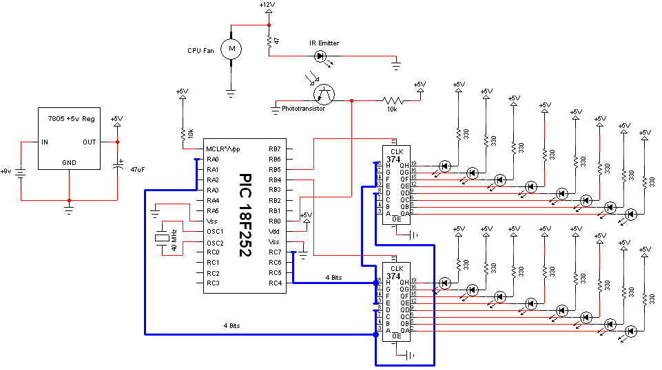
The Pyro Propeller Clock POV schematic is actually not very difficult. There are three main parts: the power supply which uses a 7805, the LED output control which uses the PIC18F252 and 74LS373 and the 'home' trigger circuit which uses an IR emitter and Phototransistor.

View Full Schematic
Schematic Specifics
Power Circuit
This standard +5v power regulation circuit makes use of the LM7805 3-pin T220 device. A DC filtering capacitor is attached to its output to prevent high frequency spikes from the power supply.
LED Output Control
The PIC 18F252 uses an 8-bit data bus system with 2 control lines to tell which 74LS373 latch to output data on the bus to turn on/off LEDs. With this design, we can only send data to one 74LS373 at a time, which just means LED output updates will be nearly simultaneous instead of 100% simultaneous.
The Home Trigger Circuit
In order to know when the system should restart displaying the current image on the propeller clock, we need a known reference point called 'home'. An IR emitter diode shines bright into a phototransistor. This turns the transistor 'On' connecting the +5v collector pin to the +0v Emitter pin. The PIC 18F252 will see this 'falling edge' transition and know right away it's back at the home location, 360°.
The Pyro Propeller Clock POV schematic is actually not very difficult. There are three main parts: the power supply which uses a 7805, the LED output control which uses the PIC18F252 and 74LS373 and the 'home' trigger circuit which uses an IR emitter and Phototransistor.
View Full Schematic
Schematic Specifics
Power Circuit
This standard +5v power regulation circuit makes use of the LM7805 3-pin T220 device. A DC filtering capacitor is attached to its output to prevent high frequency spikes from the power supply.
LED Output Control
The PIC 18F252 uses an 8-bit data bus system with 2 control lines to tell which 74LS373 latch to output data on the bus to turn on/off LEDs. With this design, we can only send data to one 74LS373 at a time, which just means LED output updates will be nearly simultaneous instead of 100% simultaneous.
The Home Trigger Circuit
In order to know when the system should restart displaying the current image on the propeller clock, we need a known reference point called 'home'. An IR emitter diode shines bright into a phototransistor. This turns the transistor 'On' connecting the +5v collector pin to the +0v Emitter pin. The PIC 18F252 will see this 'falling edge' transition and know right away it's back at the home location, 360°.