Data Latch Theory
The 74LS373 data latch is used in my design as an LED driver. The output from the latches tells the LEDs to turn on or off. Since there are 13 specific LEDs that need to be individually controlled, each LED is connected to a specific data pin on one of the latches. This pin now controls whether an LED is turned on or off.
How The 74LS373 Data Latch Works
Each data latch has two control pins: Latch Enable and Output Control. Below I will briefly describe how the control functionality works and how it will be used in the propeller clock.
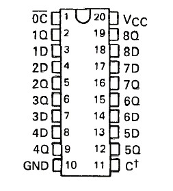
Output Control (OC) enables or disables the output pins. If they are enabled, data flows from the input to the output. If the output control is disabled, the output pins act as if they are not connected to the circuit.
Latch Enable (LE/C†) tells the 74LS373 to either take in new data or to pause the current state. When a +5v signal is applied to the LE pin, data flows freely through the 74LS373 Input to Output. When the LE pin sees a +0v (GND) signal data is stopped at the input and travels no further. Output data remains in the previous state.
How We Will Use The Data Latch
Since there are 360 specific spots that we want to output to the LEDs, we must create a function that can set the leds to a certain value and then clear them. The picture above shows the flow of data from the PIC telling the latches which LEDs to turn on at every specific 1° interval. If done correctly witht he right timing, this should create the correct pov 'optical illusion' and show up as the image we want to see.
The 74LS373 data latch is used in my design as an LED driver. The output from the latches tells the LEDs to turn on or off. Since there are 13 specific LEDs that need to be individually controlled, each LED is connected to a specific data pin on one of the latches. This pin now controls whether an LED is turned on or off.
Each data latch has two control pins: Latch Enable and Output Control. Below I will briefly describe how the control functionality works and how it will be used in the propeller clock.
Output Control (OC) enables or disables the output pins. If they are enabled, data flows from the input to the output. If the output control is disabled, the output pins act as if they are not connected to the circuit.
Latch Enable (LE/C†) tells the 74LS373 to either take in new data or to pause the current state. When a +5v signal is applied to the LE pin, data flows freely through the 74LS373 Input to Output. When the LE pin sees a +0v (GND) signal data is stopped at the input and travels no further. Output data remains in the previous state.
Since there are 360 specific spots that we want to output to the LEDs, we must create a function that can set the leds to a certain value and then clear them. The picture above shows the flow of data from the PIC telling the latches which LEDs to turn on at every specific 1° interval. If done correctly witht he right timing, this should create the correct pov 'optical illusion' and show up as the image we want to see.