Hardware Design
The schematic showed us how simple the hardware connections will be, so let's have some fun and build a quick plexi-glass box for our breadboard. A few holes will get drilled across the box to hold our sensor, speaker and LEDs in place.
Assemble The Circuit
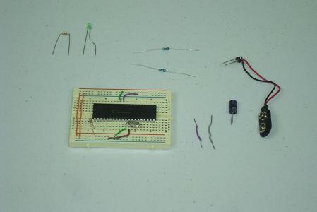
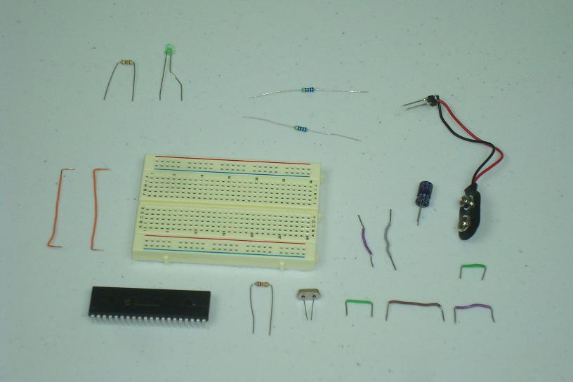
Gather all the electrical parts for the breadboard and assemble them together according to the schematic.

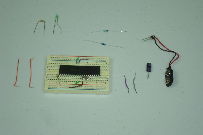
·The parts above should show you how simple this process should be. First I connected the basic PIC parts to the power, ground and clock.

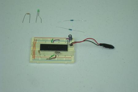
·Next I added the power, ground bus connections for both sides of the breadboard.
·Now I put in the battery connector and associated power connections.
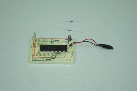
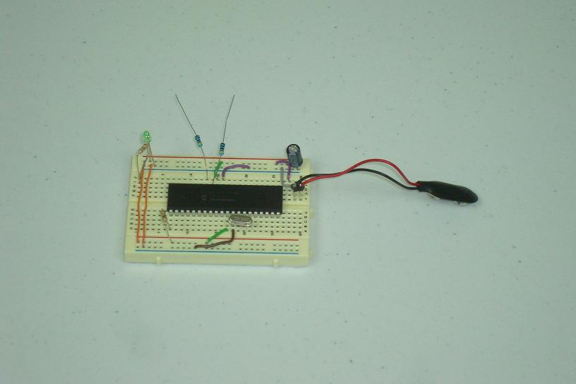
·The power led came next, just a resistor and LED.
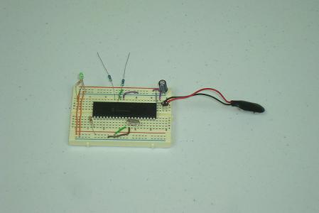
·The final connections for this time are the two resistors for the two front leds.
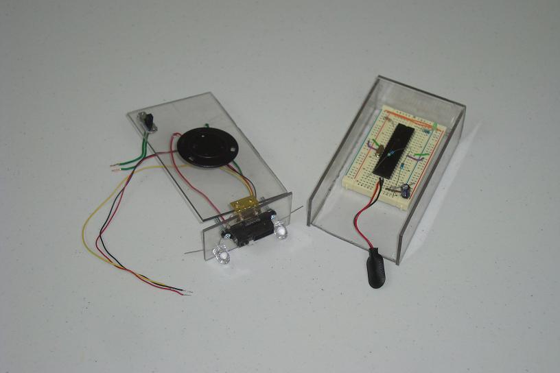
·With both pieces of this project completed, the trickiest part is connecting them together.
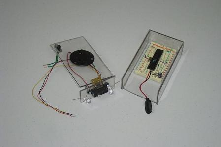
·Above you can see the top and bottom pieces, using some needle nose pliers I connected the power switch and other tricky connections before glueing the top with E-Poxy to the enclosure walls.
·The final box looks good and has the 'see-thru' look that I wanted.
The schematic showed us how simple the hardware connections will be, so let's have some fun and build a quick plexi-glass box for our breadboard. A few holes will get drilled across the box to hold our sensor, speaker and LEDs in place.
Assemble The Circuit
Gather all the electrical parts for the breadboard and assemble them together according to the schematic.
·The parts above should show you how simple this process should be. First I connected the basic PIC parts to the power, ground and clock.
·Next I added the power, ground bus connections for both sides of the breadboard.

·Now I put in the battery connector and associated power connections.

·The power led came next, just a resistor and LED.
·The final connections for this time are the two resistors for the two front leds.
·With both pieces of this project completed, the trickiest part is connecting them together.
·Above you can see the top and bottom pieces, using some needle nose pliers I connected the power switch and other tricky connections before glueing the top with E-Poxy to the enclosure walls.
·The final box looks good and has the 'see-thru' look that I wanted.