Schematic Overview
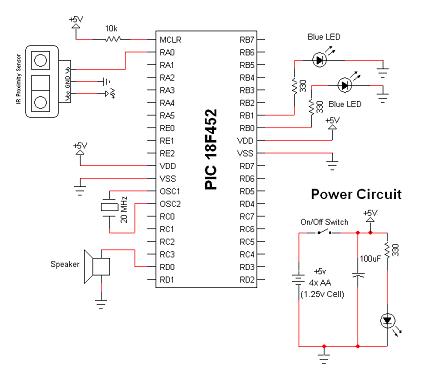
The IR Theremin hardware schematic is deliciously simple in that the main input and output devices do not require many connections. This is usually a mixed blessing because less hardware, often means more software. The main devices used in the circuit are the 18F452, 2Y0A21/GP2D120 IR Sensor and the headphone speaker.
View Full Schematic
Schematic Specifics
Power Circuit
The power circuit here is just batteries. No voltage regulator was used because the batteries I have are all +1.2v, so 4 AA Batteries x +1.2v = +4.8v which is within specification with the PIC and IR sensor.
IR Proximity Sensor Circuit
The IR Sensor only has three connections: Power, Ground and Output to the PIC's pin 2 (RA0). This is set as an analog input for the A-to-D converter in the PIC.
Speaker Connection
The connection to the speaker is one side going directly to ground and the other side of the speaker connecting to the PIC's pin 19 (RD0). The firmware will tell this pin to alternate between on and off at certain frequencies to create the proper pitch output to the speaker.
The IR Theremin hardware schematic is deliciously simple in that the main input and output devices do not require many connections. This is usually a mixed blessing because less hardware, often means more software. The main devices used in the circuit are the 18F452, 2Y0A21/GP2D120 IR Sensor and the headphone speaker.

View Full Schematic
Schematic Specifics
Power Circuit
The power circuit here is just batteries. No voltage regulator was used because the batteries I have are all +1.2v, so 4 AA Batteries x +1.2v = +4.8v which is within specification with the PIC and IR sensor.
IR Proximity Sensor Circuit
The IR Sensor only has three connections: Power, Ground and Output to the PIC's pin 2 (RA0). This is set as an analog input for the A-to-D converter in the PIC.
Speaker Connection
The connection to the speaker is one side going directly to ground and the other side of the speaker connecting to the PIC's pin 19 (RD0). The firmware will tell this pin to alternate between on and off at certain frequencies to create the proper pitch output to the speaker.