The Common Emitter Amplifier
Aside from acting as on/off switches, transistors can also be used as amplifiers. Whole ranges of different transistors exist for different types of amplification. The Common-Emitter Amplifier (CE Amp for short), is probably the most common type of amplifier seen in standard electronics. The basic idea at work for amplifier used in the FM Bug is that the 1 Megaohm resistor biases the transistor in a way that when the Audio input goes into the base pin of the BC547 it is multiplied to be many times larger by the time it hits the Collector point of the transistor. Try using different resistance values other than 1 Megaohm and you'll see differences in the amplification factor.
Simulating The Simple CE Amplifier
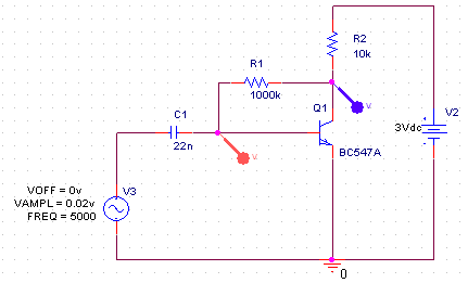
Spice is used here to simulate the amplifier circuit seen in the schematic for the FM transmitter in this project. Above I've already drawn out the amplifier portion of the circuit using Spice. The two points of interest are [1] where the red probe is, which is the filtered audio input and [2] where the purple probe is, which is the amplified signal coming out of the transistor.
FM Bug Amplifier Simulation Results
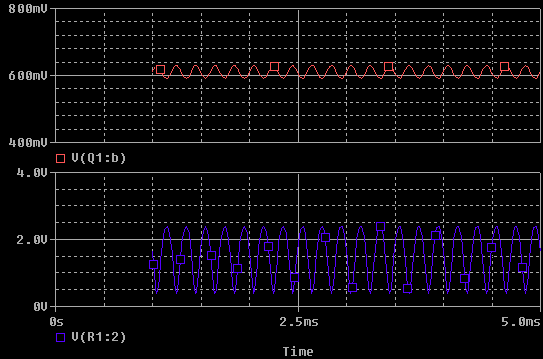
The audio input, a simluated sin wave at 5000 Hz shows up at about 50 milivolts peak to peak (red line graph). This is tiny, but about how much voltage the electret microphone puts out with the design seen in the schematic.
The purple line graph shows the amplified signal coming out of the transistor. The signal is about 1.2 volts peak to peak which is over 50x larger than the input signal. Clearly the signal has been amplified to a much larger value than it was at before.
Aside from acting as on/off switches, transistors can also be used as amplifiers. Whole ranges of different transistors exist for different types of amplification. The Common-Emitter Amplifier (CE Amp for short), is probably the most common type of amplifier seen in standard electronics. The basic idea at work for amplifier used in the FM Bug is that the 1 Megaohm resistor biases the transistor in a way that when the Audio input goes into the base pin of the BC547 it is multiplied to be many times larger by the time it hits the Collector point of the transistor. Try using different resistance values other than 1 Megaohm and you'll see differences in the amplification factor.
Simulating The Simple CE Amplifier
Spice is used here to simulate the amplifier circuit seen in the schematic for the FM transmitter in this project. Above I've already drawn out the amplifier portion of the circuit using Spice. The two points of interest are [1] where the red probe is, which is the filtered audio input and [2] where the purple probe is, which is the amplified signal coming out of the transistor.
The audio input, a simluated sin wave at 5000 Hz shows up at about 50 milivolts peak to peak (red line graph). This is tiny, but about how much voltage the electret microphone puts out with the design seen in the schematic.
The purple line graph shows the amplified signal coming out of the transistor. The signal is about 1.2 volts peak to peak which is over 50x larger than the input signal. Clearly the signal has been amplified to a much larger value than it was at before.