The Overall Design
The design that we'll go with for this project is really a 4-step process. The image below illustrates it perfectly but I'll also include an explanation of the process from input to output below. In this theory section, I'm going to assume you already know how an IR proximity sensor works. If you've never used one before, please check out my IR Sharp Range Sensor tutorial so this stuff makes more sense!
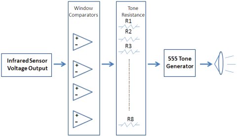
First, the IR proximity sensor outputs a voltage, then the window comparators will compare that voltage to their constant upper and lower limit voltages (set using voltage dividers with 2 resistors). If the voltage output (by the IR proximity sensor) is inside of the two voltages or 'window', that comparator will output to a certain resistor which sets a specific tone for the 555 tone generator to output to the speaker. A little more than a mouthful, but I'll explain in more detail.
Window Comparators
Since we'll be using window comparators to convert the IR proximity sensor output to a more understandable digital format, we first need to know what a window comparator is and how it works. Below is an example schematic of a window comparator. It uses two op-amps: one set of voltage dividing resisitors that yield reference voltage of +3.3v and another set that yields +2.5v.
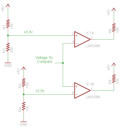
The way the window comparator works is that the two set voltages (+2.5v and +3.3v) are used as an lower limit and upper limit, respectively. If the voltage that we are comparing to these two limits is between them, both comparators will output a 1 (seen in the truth table below). This means there is a 'window' of voltage where the comparators can both output a logic 1. If the voltage that we are comparing to the limits is outside of the window, then the comparators will never both output a logic 1. Now we have our digital signals!
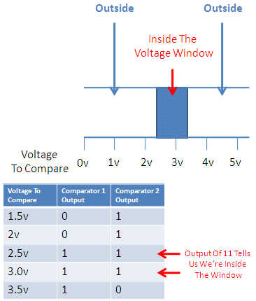
Since the comparators output logic 0 or logic 1, which are digital signals, we can now do all of our thinking in the digital domain. Hurray! Now let's look at how the tone generation will work using the 555 timer.
The design that we'll go with for this project is really a 4-step process. The image below illustrates it perfectly but I'll also include an explanation of the process from input to output below. In this theory section, I'm going to assume you already know how an IR proximity sensor works. If you've never used one before, please check out my IR Sharp Range Sensor tutorial so this stuff makes more sense!

First, the IR proximity sensor outputs a voltage, then the window comparators will compare that voltage to their constant upper and lower limit voltages (set using voltage dividers with 2 resistors). If the voltage output (by the IR proximity sensor) is inside of the two voltages or 'window', that comparator will output to a certain resistor which sets a specific tone for the 555 tone generator to output to the speaker. A little more than a mouthful, but I'll explain in more detail.
Window Comparators
Since we'll be using window comparators to convert the IR proximity sensor output to a more understandable digital format, we first need to know what a window comparator is and how it works. Below is an example schematic of a window comparator. It uses two op-amps: one set of voltage dividing resisitors that yield reference voltage of +3.3v and another set that yields +2.5v.
The way the window comparator works is that the two set voltages (+2.5v and +3.3v) are used as an lower limit and upper limit, respectively. If the voltage that we are comparing to these two limits is between them, both comparators will output a 1 (seen in the truth table below). This means there is a 'window' of voltage where the comparators can both output a logic 1. If the voltage that we are comparing to the limits is outside of the window, then the comparators will never both output a logic 1. Now we have our digital signals!
Since the comparators output logic 0 or logic 1, which are digital signals, we can now do all of our thinking in the digital domain. Hurray! Now let's look at how the tone generation will work using the 555 timer.