Schematic Overview
The schematic for this project is slightly more complicated. The full schematic can be seen below, click on the image for the larger version as it's hard to see all the details in the smaller version.
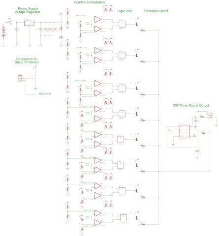
View Full Schematic
Schematic Specifics
+5v Power Regulator and On/Off Toggle Switch
A 7805 +5v regulator is used for this project as everything here will be running off of +5v.
Sensor Input Connector
The IR Proximity Sensor has a 3 pin connector that is super simple, Vsupply, Gnd, Vout. Vsupply is connected to +5v power and Gnd to Ground. Vout will be connecting to each of the window comparators.
Window Comparator
16 op-amps (from the LM339 IC) are used as 8 window comparators. This creates 8 windows with an upper and lower voltage limit, when the sensor voltage is in between the two, both comparators output a logic 1.
And Gates
Since we need 1 logic signal from the window comparators, we will AND each of the two window comparator outputs together so that when the '11' case comes the AND gate outputs a 1 and for all other cases, output is a 0.
Transistor/Resistor Tone Selection
From the AND gates, the signal logic signal will hit one of the 8 transistors turning it on. This will in turn connect +5v power to a resistor connected to the tone generator circuit.
555 Timer Tone Generator
Depending on which resistor has been triggered through a transistor, the 555 tone generator will output a different pitch of tone. Different resistors yield different tones: the higher the resistance value the lower the tone is.
The schematic for this project is slightly more complicated. The full schematic can be seen below, click on the image for the larger version as it's hard to see all the details in the smaller version.
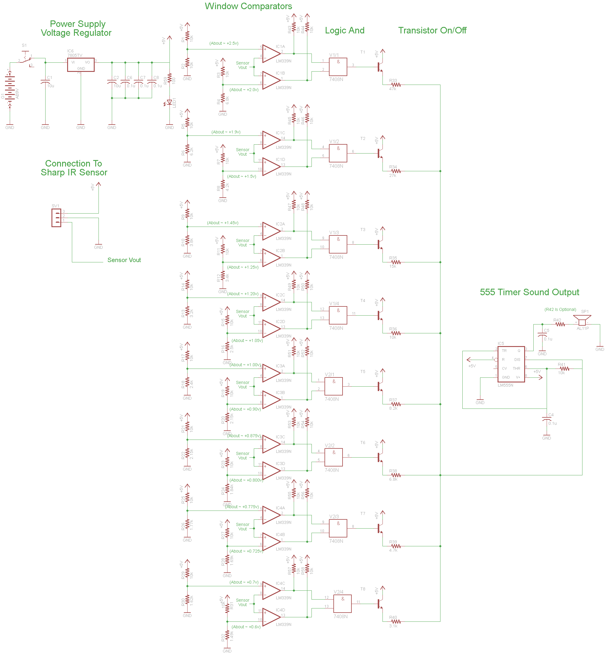
View Full Schematic
Schematic Specifics
+5v Power Regulator and On/Off Toggle Switch
A 7805 +5v regulator is used for this project as everything here will be running off of +5v.
Sensor Input Connector
The IR Proximity Sensor has a 3 pin connector that is super simple, Vsupply, Gnd, Vout. Vsupply is connected to +5v power and Gnd to Ground. Vout will be connecting to each of the window comparators.
Window Comparator
16 op-amps (from the LM339 IC) are used as 8 window comparators. This creates 8 windows with an upper and lower voltage limit, when the sensor voltage is in between the two, both comparators output a logic 1.
And Gates
Since we need 1 logic signal from the window comparators, we will AND each of the two window comparator outputs together so that when the '11' case comes the AND gate outputs a 1 and for all other cases, output is a 0.
Transistor/Resistor Tone Selection
From the AND gates, the signal logic signal will hit one of the 8 transistors turning it on. This will in turn connect +5v power to a resistor connected to the tone generator circuit.
555 Timer Tone Generator
Depending on which resistor has been triggered through a transistor, the 555 tone generator will output a different pitch of tone. Different resistors yield different tones: the higher the resistance value the lower the tone is.