Hardware Design
The hardware design and construction portion of this project is a single section on this page. Keep scrolling down for the hardware goodness!
Putting Everything Together
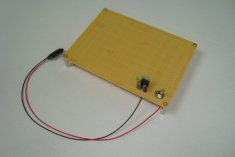
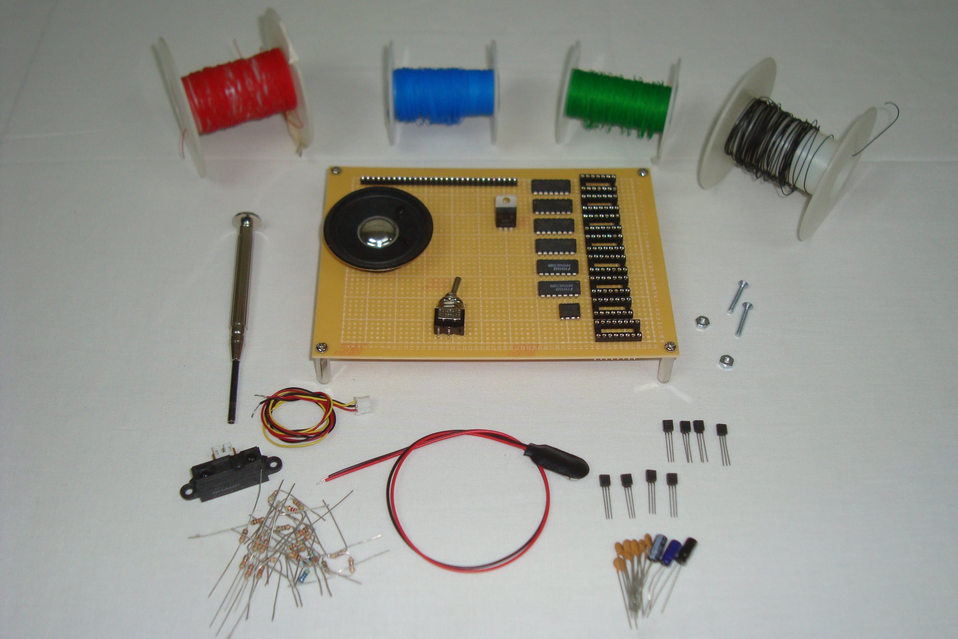
Since this is an all hardware project, you want to take care with every step to make sure you get connections wired to the right spots. If you get one thing wrong the whole system will work incorrectly and ruin your day. No one wants to spend hours debugging hardware! So take a second look at the schematic and get ready to start building! First gather your parts together as I have here:

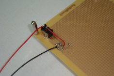
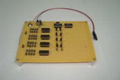
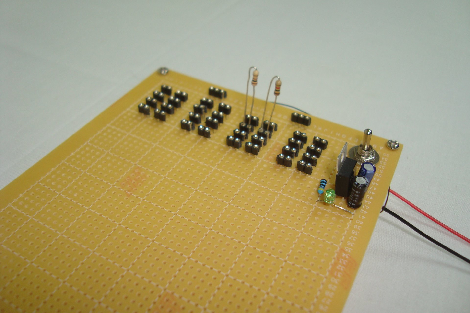
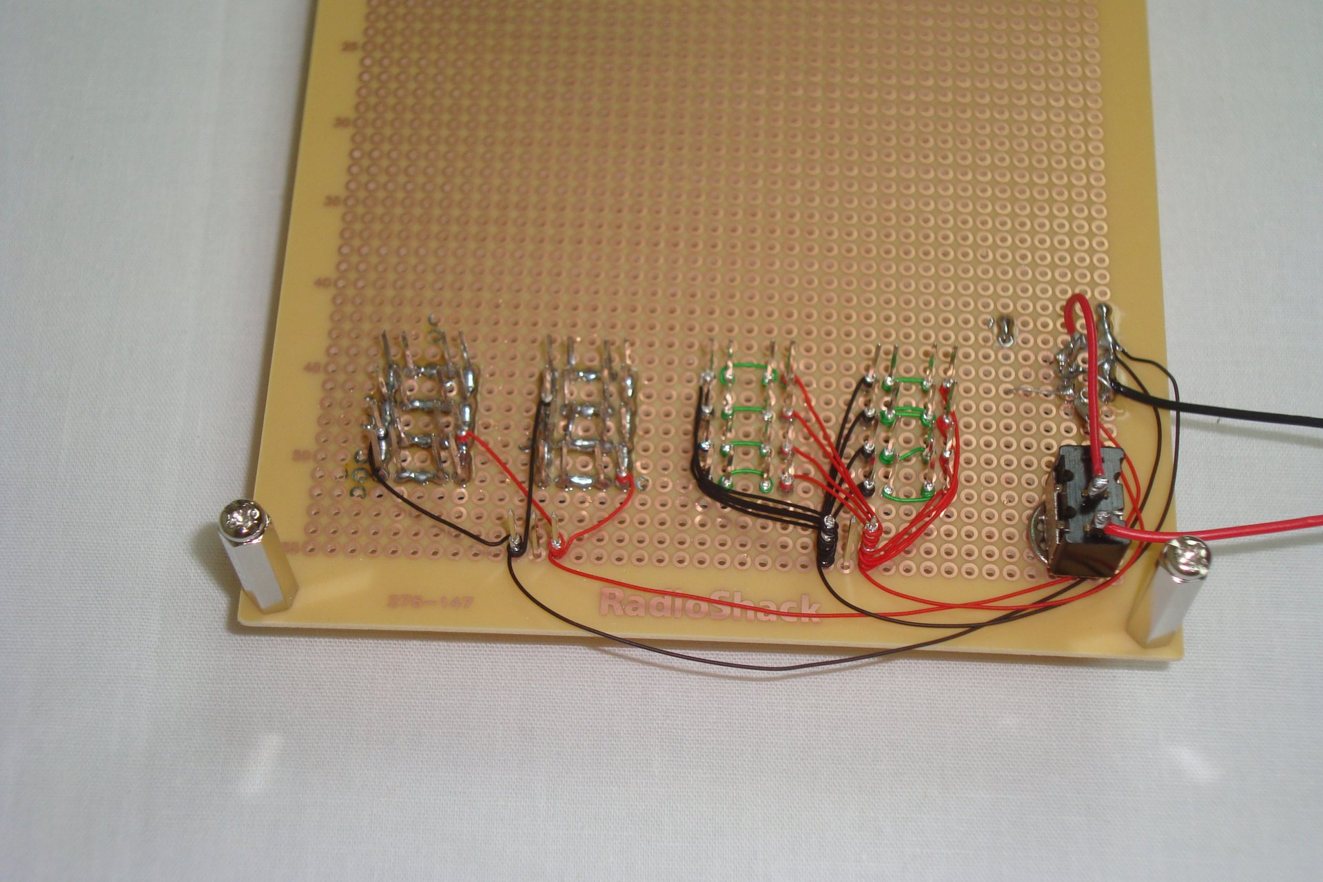
First the power circuit is assembled and soldered to the board.
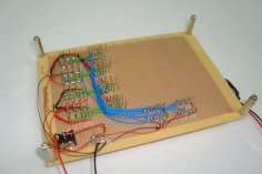
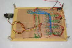
Next, we took a bunch of SIPs and made the voltage dividers for the window comparators. There are 16 voltage dividers in total and 32 places for resistors. If you look closely at the bottom of the board, you can see how we wire-wrapped the entire upper portion, but soldered most of the bottom portion. You can do it either way!

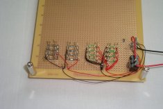
The LM339's and 2 7408 ICs are added to the board and connected to voltage dividers to form the window comparator circuit an tone selection.
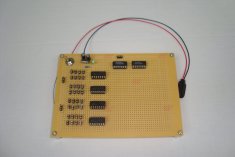
Now the tone resistors and switch transistor are added.
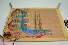
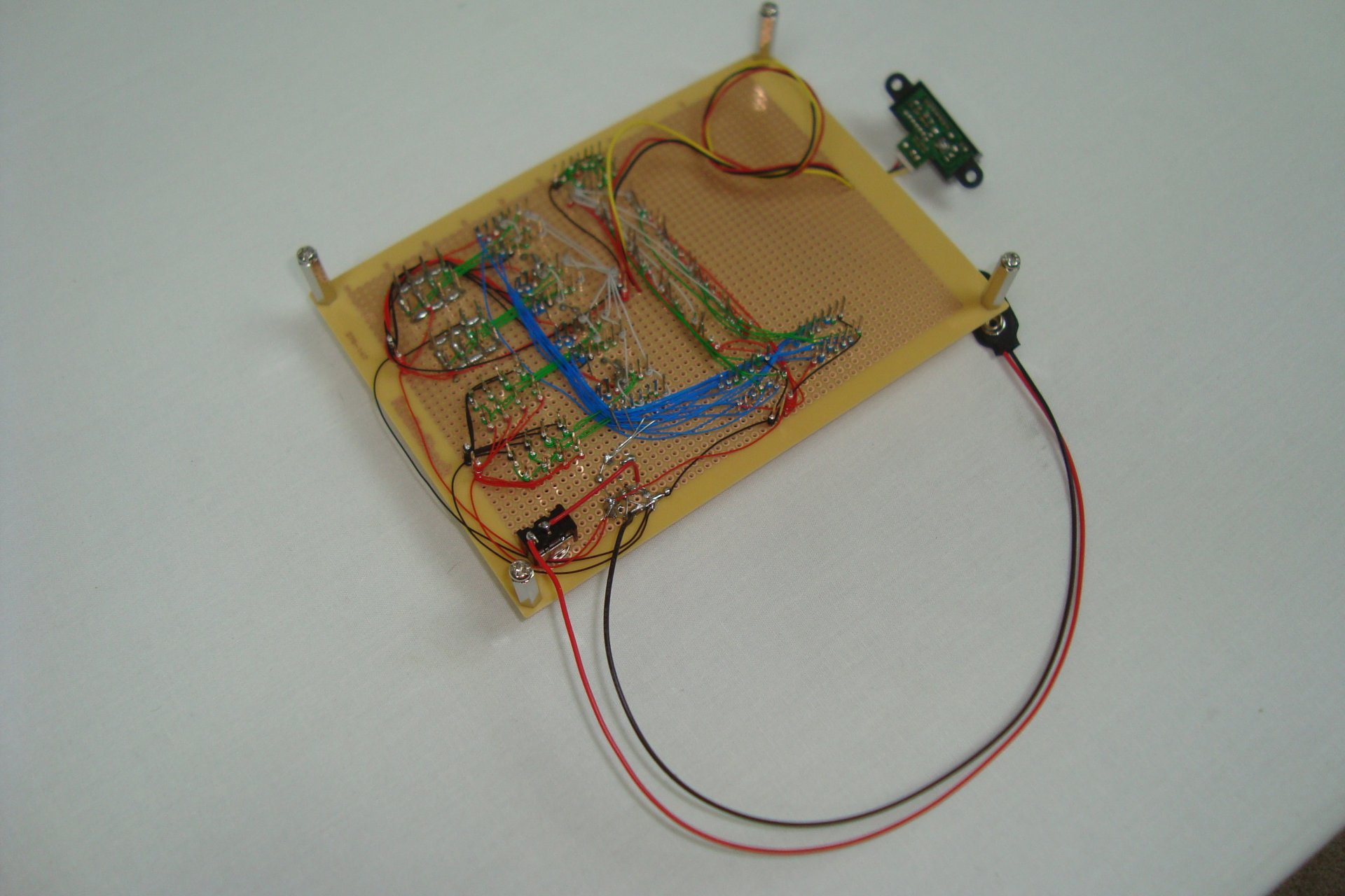
Now, we'll finally add all the resistors to the board. The sensor is also added and connected to all of the window comparators. The 555 timer a-stable multivibrator is also connected.
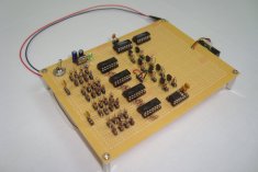

Lastly, we add the speaker and there we have it. The schematic circuit is complete and the theremin should work.
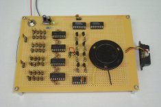
Now the system is ready to be flipped on. Turn the power switch and see how it works...or watch the video in the next section.
The hardware design and construction portion of this project is a single section on this page. Keep scrolling down for the hardware goodness!
Putting Everything Together
Since this is an all hardware project, you want to take care with every step to make sure you get connections wired to the right spots. If you get one thing wrong the whole system will work incorrectly and ruin your day. No one wants to spend hours debugging hardware! So take a second look at the schematic and get ready to start building! First gather your parts together as I have here:
First the power circuit is assembled and soldered to the board.


Next, we took a bunch of SIPs and made the voltage dividers for the window comparators. There are 16 voltage dividers in total and 32 places for resistors. If you look closely at the bottom of the board, you can see how we wire-wrapped the entire upper portion, but soldered most of the bottom portion. You can do it either way!
The LM339's and 2 7408 ICs are added to the board and connected to voltage dividers to form the window comparator circuit an tone selection.


Now the tone resistors and switch transistor are added.


Now, we'll finally add all the resistors to the board. The sensor is also added and connected to all of the window comparators. The 555 timer a-stable multivibrator is also connected.

Lastly, we add the speaker and there we have it. The schematic circuit is complete and the theremin should work.


Now the system is ready to be flipped on. Turn the power switch and see how it works...or watch the video in the next section.