Schematic Overview
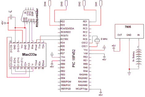
This is the schematic of the circuit that we'll create. There are 4 core devices: the PIC 18F452, MAX 233a, LM7805 & RS232 Header. These devices work together to receive & interpret the serial input & output to control the rc car based off of the commands input.

View Full Schematic
Schematic Specifics
The Brains - PIC 18F452
The PIC acts as the brains of the operations. It receives the straight serial input from the MAX 233a through PORTC. The PIC acts only as a receiver and never sends anything back to the host computer, although it could as its wired to do so. PORTD of the pic has 4 pins wired to the single pin on the transmitter that we spoke of before. To be specific (reguarding to the previous schematic) these four pins are wired right inbetween resistors D6, D7, D8 & D9 and their respective switches (SW1-SW4).
RS232 Conversion - MAX 233a
This device is as much a relic as it is tried and true. It creates the proper voltage levels necessary to perform serial communication with the RS232 standard that pretty much all desktops/laptops have anymore (if your laptop even has a serial port!). RS232 doesn't follow the 0v/5v standard as the pic uses so this device is needed to translate over.
Power Circuit - 7805
Not a spectacular device, however still very important. The LM7805 makes sure a steady +5v signal is output to the devices. We put a cap across the input & outputs to make sure that the signal is indeed 'clean'.
Connection Ease - RS232 Header
Again, not entirely crucial, however it makes life much easier. The RS232 header only has 3 wires connecting to it, but it makes it significantly easier to a standard db-9 serial cable from the new transmitter we make to our host computer.
This is the schematic of the circuit that we'll create. There are 4 core devices: the PIC 18F452, MAX 233a, LM7805 & RS232 Header. These devices work together to receive & interpret the serial input & output to control the rc car based off of the commands input.

View Full Schematic
Schematic Specifics
The Brains - PIC 18F452
The PIC acts as the brains of the operations. It receives the straight serial input from the MAX 233a through PORTC. The PIC acts only as a receiver and never sends anything back to the host computer, although it could as its wired to do so. PORTD of the pic has 4 pins wired to the single pin on the transmitter that we spoke of before. To be specific (reguarding to the previous schematic) these four pins are wired right inbetween resistors D6, D7, D8 & D9 and their respective switches (SW1-SW4).
RS232 Conversion - MAX 233a
This device is as much a relic as it is tried and true. It creates the proper voltage levels necessary to perform serial communication with the RS232 standard that pretty much all desktops/laptops have anymore (if your laptop even has a serial port!). RS232 doesn't follow the 0v/5v standard as the pic uses so this device is needed to translate over.
Power Circuit - 7805
Not a spectacular device, however still very important. The LM7805 makes sure a steady +5v signal is output to the devices. We put a cap across the input & outputs to make sure that the signal is indeed 'clean'.
Connection Ease - RS232 Header
Again, not entirely crucial, however it makes life much easier. The RS232 header only has 3 wires connecting to it, but it makes it significantly easier to a standard db-9 serial cable from the new transmitter we make to our host computer.