The Theory
The theory for how this motor control system works will be described in two parts. The first part describes the input signal called PWM short for Pulse with Modulation and the second will describe which pulses go where to control speed and direction.
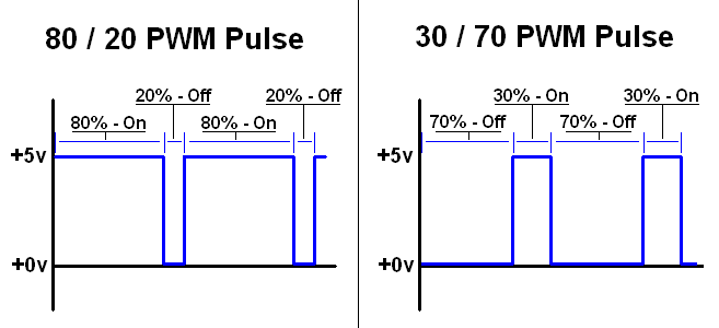
PWM Explained - Pulse With Modulation
The two images above show you two different PWM signals. The first signal is "on" 80% of the time. That means it is at +5v for 80% of the period of the signal. This is a powerful signal and it would make a motor run very fast. The second image shows you a signal similar to the first, but it is only on 30% of the time. It is at +0v for 70% of the period of the signal. Since this PWM signal is in an 'off' state for the majority of the time, it would make a motor run much slower than the first PWM.
SN754410 PWM Input

Looking at one side of the SN754410, we have a motor connected to 1Y and 2y. A PWM signal that is 80% on // 20% off is input into 1A. The corresponding output to the motor makes it turn very fast (almost full speed) in the clockwise direction.
If we look at the same setup but change the input PWM to 30% on // 70% off into the other pin, 2A, the motor will spin counter-clockwise rather slowly, at about 1/3 the motor's full speed. The motor spins in the opposite direction because the current is being input on the other side of the motor (pin 2A), thusly it flows the opposite direction through the motor compared to the first example.
XBee Wireless 8-Bit Packet
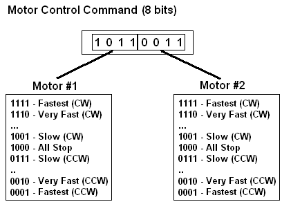
Each successful transmission using the XBee modules will consist of 8 bits of data. To make this system as beginner friendly as possible a super simple command structure was built for telling the receiver PIC how to control the motors. Each direction CW - Clockwise, CCW - Counter-Clockwise, has 7 speed settings from 001 to 111.
The theory for how this motor control system works will be described in two parts. The first part describes the input signal called PWM short for Pulse with Modulation and the second will describe which pulses go where to control speed and direction.
The two images above show you two different PWM signals. The first signal is "on" 80% of the time. That means it is at +5v for 80% of the period of the signal. This is a powerful signal and it would make a motor run very fast. The second image shows you a signal similar to the first, but it is only on 30% of the time. It is at +0v for 70% of the period of the signal. Since this PWM signal is in an 'off' state for the majority of the time, it would make a motor run much slower than the first PWM.
Looking at one side of the SN754410, we have a motor connected to 1Y and 2y. A PWM signal that is 80% on // 20% off is input into 1A. The corresponding output to the motor makes it turn very fast (almost full speed) in the clockwise direction.
If we look at the same setup but change the input PWM to 30% on // 70% off into the other pin, 2A, the motor will spin counter-clockwise rather slowly, at about 1/3 the motor's full speed. The motor spins in the opposite direction because the current is being input on the other side of the motor (pin 2A), thusly it flows the opposite direction through the motor compared to the first example.
XBee Wireless 8-Bit Packet
Each successful transmission using the XBee modules will consist of 8 bits of data. To make this system as beginner friendly as possible a super simple command structure was built for telling the receiver PIC how to control the motors. Each direction CW - Clockwise, CCW - Counter-Clockwise, has 7 speed settings from 001 to 111.