Hardware Design
There are two pieces of hardware that we need to assemble together, the transmitter and the receiver. What I'll do is assemble each piece of hardware step by step following the schematic and give you some photos to follow along with to see how I did it.
The Transmitter
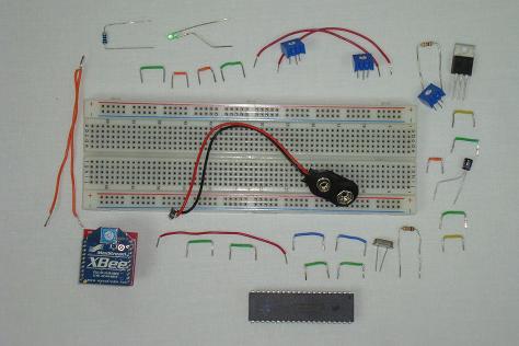
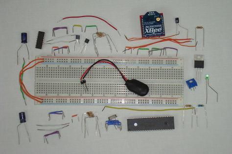
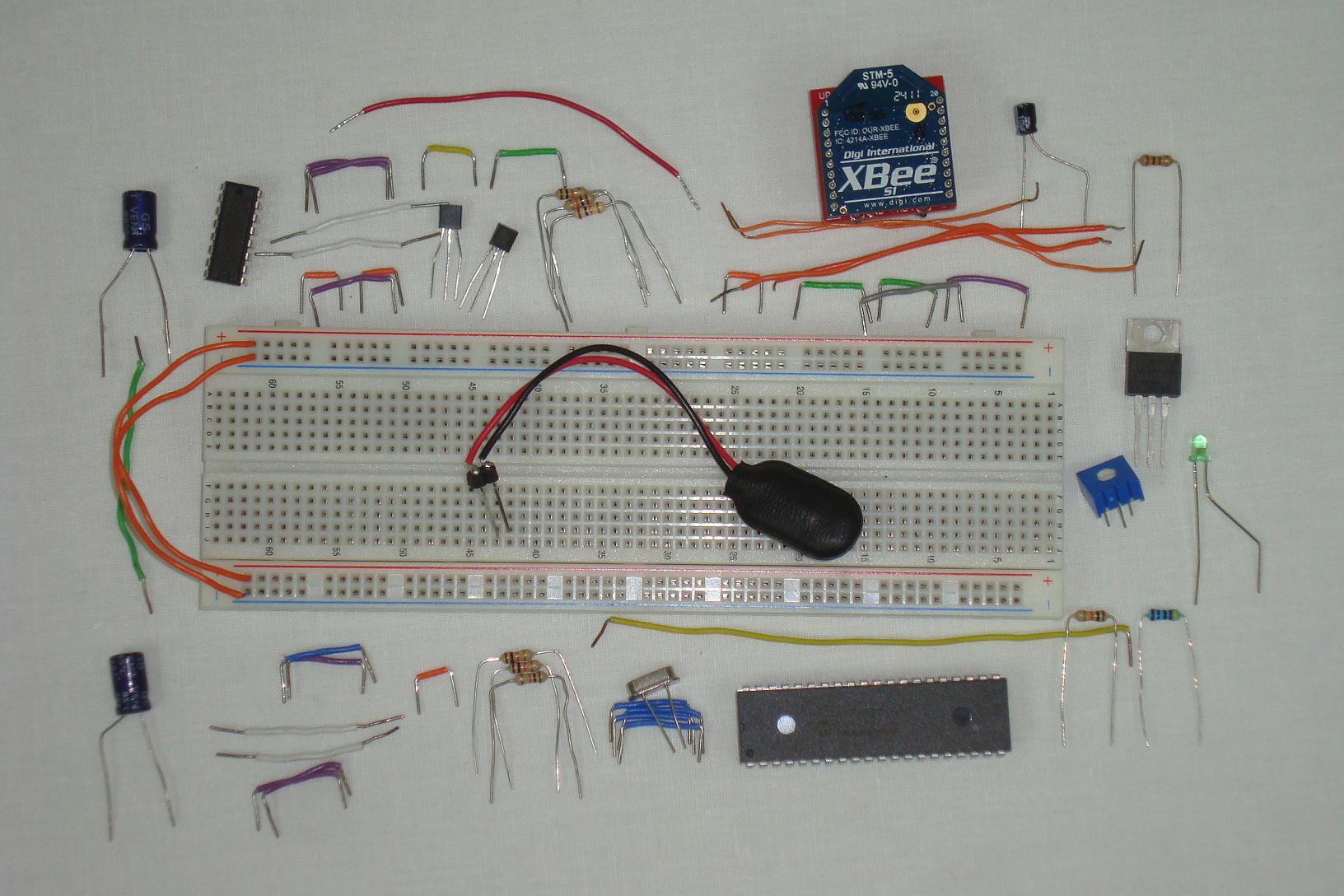
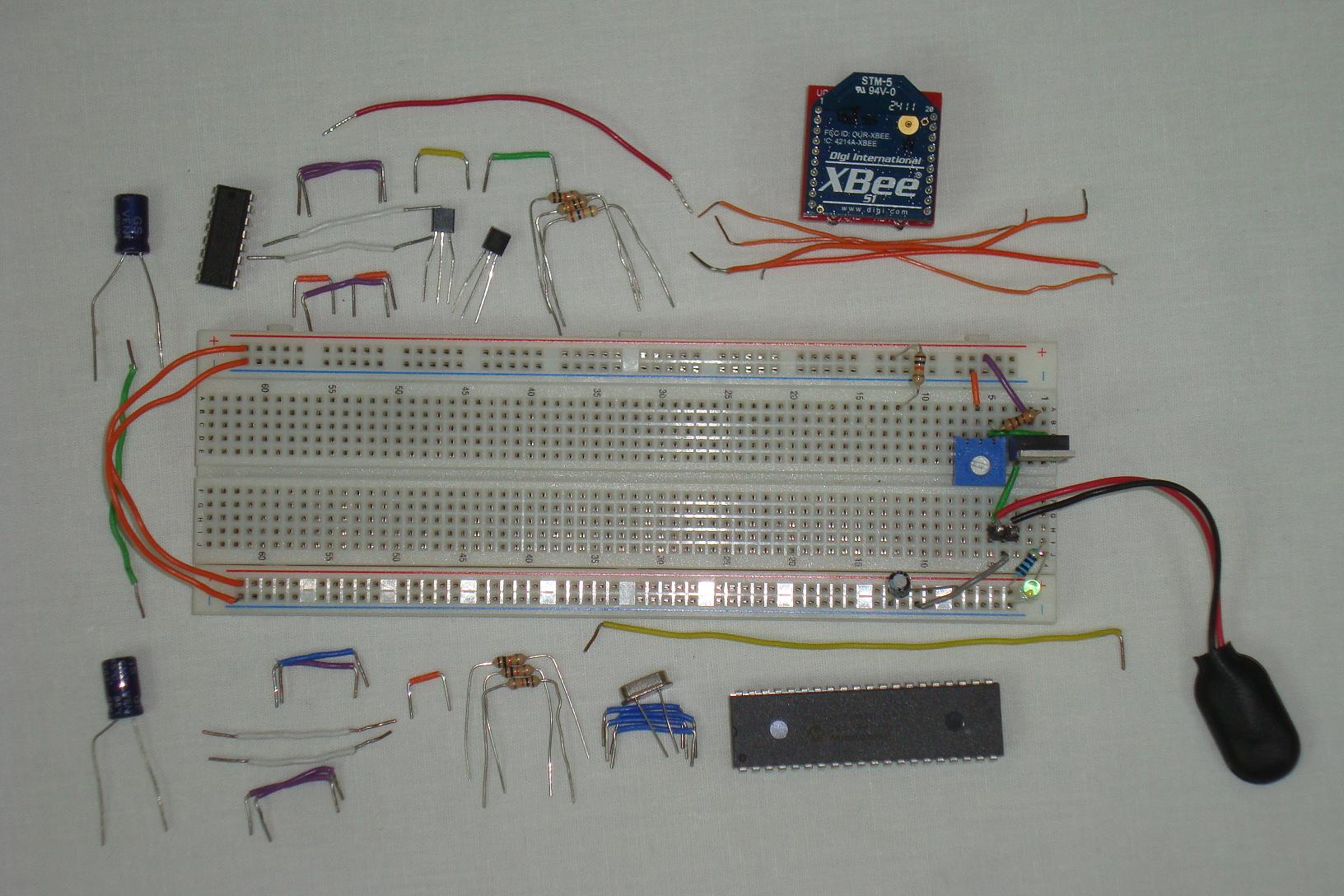
First we'll build the transmitter circuit, gather all the parts for the transmitter as I have below.
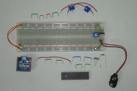
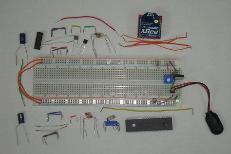
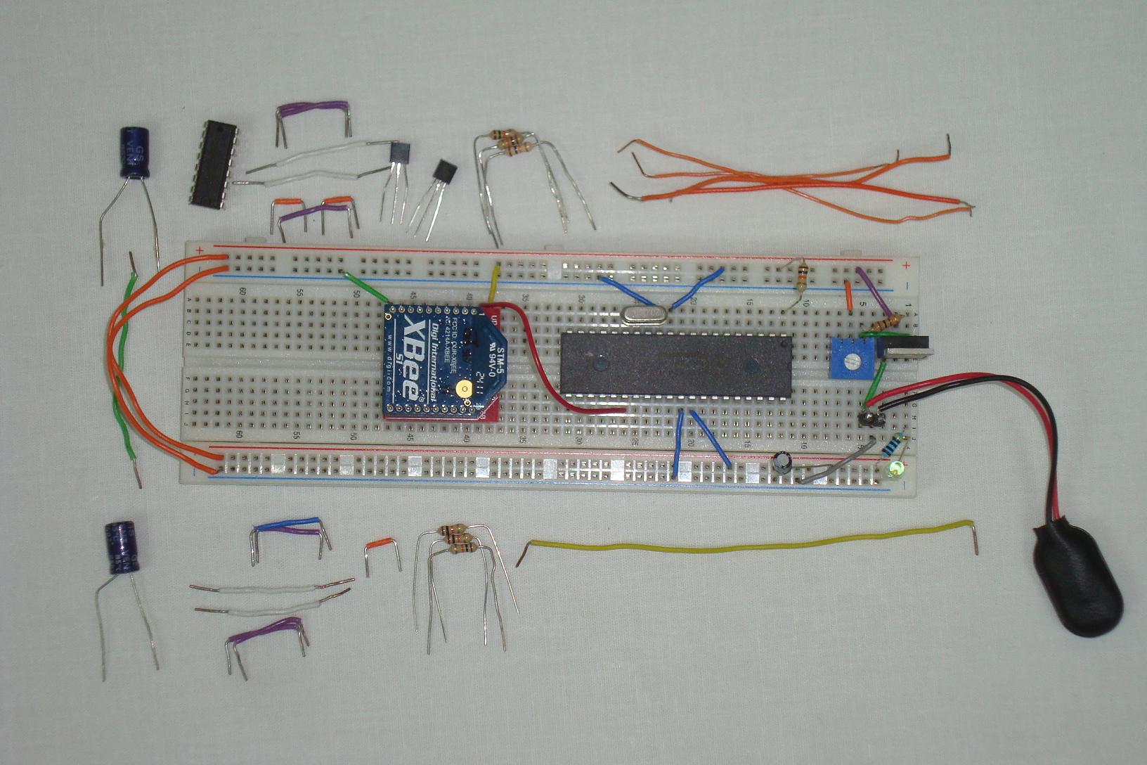
·The Power Supply circuit for regulating +3.3v is always connected together first.
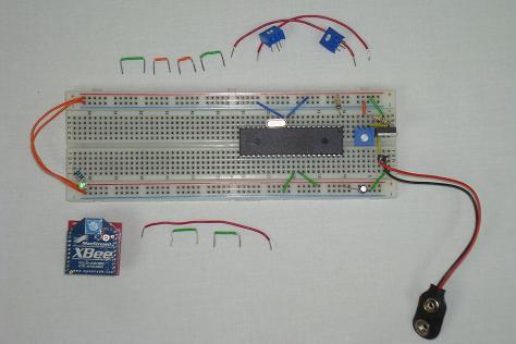
·Then the basic PIC circuit is added.
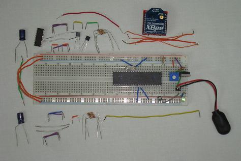
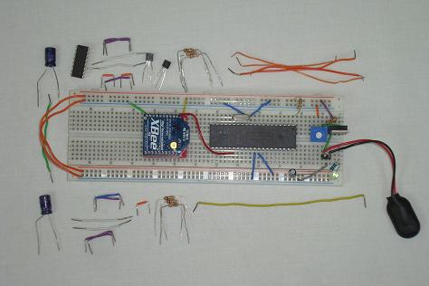
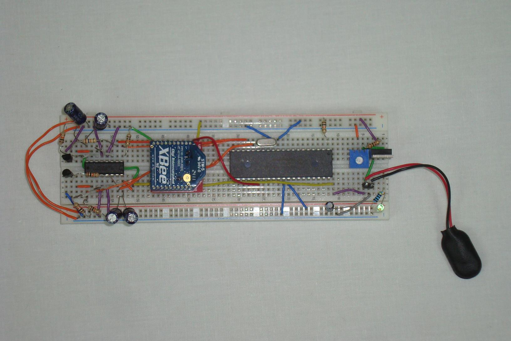
·The XBee module is connected to power, ground and USART Tx.
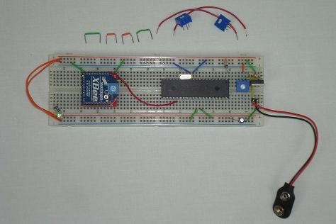
·The 2 trimpouts are connected to power, ground and output to the PIC's PIN 2 and 3.
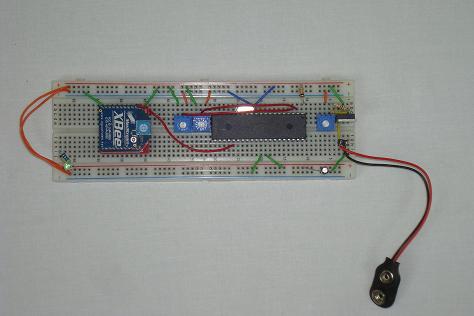
·The transmitter is complete! Let's move onward and build the receiver.
The Receiver
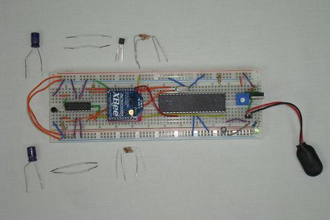
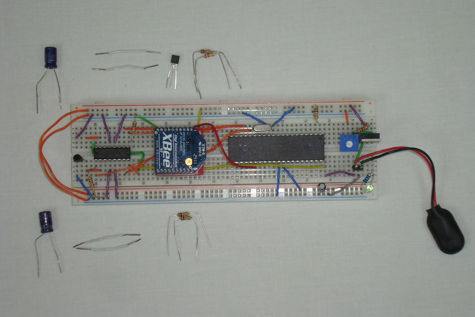
·Same as before, the power supply regulator circuit is connected first.
·Then the PIC circuit is added.
·The XBee receiver is connected to power, ground and input to the PIC's USART Rx pin.
·Next, we start to assmeble most of the motor control circuit.
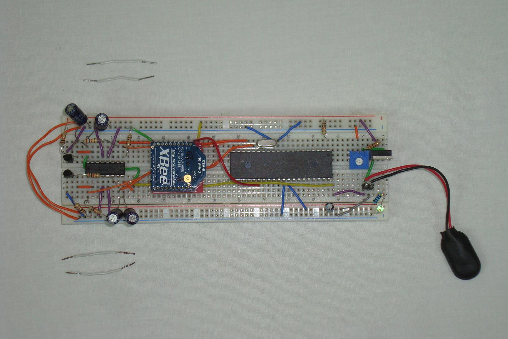
·Some additional connections and capacitors are added.
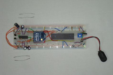
·And the final 4 wires for connecting to the motors are added.

·Both pieces of hardware have been assembled, now let's take a look at the software side of what we need to do.
There are two pieces of hardware that we need to assemble together, the transmitter and the receiver. What I'll do is assemble each piece of hardware step by step following the schematic and give you some photos to follow along with to see how I did it.
The Transmitter
First we'll build the transmitter circuit, gather all the parts for the transmitter as I have below.
·The Power Supply circuit for regulating +3.3v is always connected together first.
·Then the basic PIC circuit is added.
·The XBee module is connected to power, ground and USART Tx.
·The 2 trimpouts are connected to power, ground and output to the PIC's PIN 2 and 3.
·The transmitter is complete! Let's move onward and build the receiver.
The Receiver
·Same as before, the power supply regulator circuit is connected first.
·Then the PIC circuit is added.

·The XBee receiver is connected to power, ground and input to the PIC's USART Rx pin.
·Next, we start to assmeble most of the motor control circuit.
·Some additional connections and capacitors are added.
·And the final 4 wires for connecting to the motors are added.
·Both pieces of hardware have been assembled, now let's take a look at the software side of what we need to do.