Schematic Overview
There are two schematics for this project, one for the transmitter and one for the receiver. The transmitter is fairly simple, and the receiver is a little more complicated. The main parts in the schematic are the PIC 18LF4520, XBee Modules and SN754410NE.
Transmitter Schematic
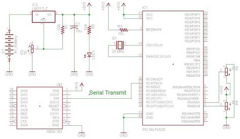
View Full Schematic
Trimpot Input Into The PIC
The input we will give to the PIC's will come from two standard trimpot outputs. The trimpot is tied to power and ground, with the middle pin being a variable voltage send to the PIC's A/D converter on pin RA0. A second trimpot is connected exactly the same and enters the PIC's second A/D converter on pin RA1.
Xbee Module Wireless Output
The PIC will then translate this input to an integer of value 0-7 and send it via the PIC's serial communication module at 9600 BPS to the Xbee's Din pin.
Receiver Schematic
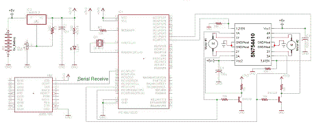
View Full Schematic
SN754410NE Control Signals
Each motor requires 1 enable input and two PWM inputs. We'll use the PIC's PORTD RD0 and RD1 as enable lines and the CCP module's CCP1 and CCP2 will be used to output PWM to the motor controller. Since the motor controller needs to see a differential PWM, we'll use 2 2N2222 transistors, to invert each CCP output and connect it to the SN754410.
Xbee Module Wireless Input
The Xbee receiver will automatically connect with the transmitter and begin receiving data. All data will be received and output via the Dout pin on the Xbee module. The Dout pin is conneceted directly to the PIC's Rx pin so that the PIC can catch the data.
There are two schematics for this project, one for the transmitter and one for the receiver. The transmitter is fairly simple, and the receiver is a little more complicated. The main parts in the schematic are the PIC 18LF4520, XBee Modules and SN754410NE.
Transmitter Schematic
View Full Schematic
Trimpot Input Into The PIC
The input we will give to the PIC's will come from two standard trimpot outputs. The trimpot is tied to power and ground, with the middle pin being a variable voltage send to the PIC's A/D converter on pin RA0. A second trimpot is connected exactly the same and enters the PIC's second A/D converter on pin RA1.
Xbee Module Wireless Output
The PIC will then translate this input to an integer of value 0-7 and send it via the PIC's serial communication module at 9600 BPS to the Xbee's Din pin.
Receiver Schematic
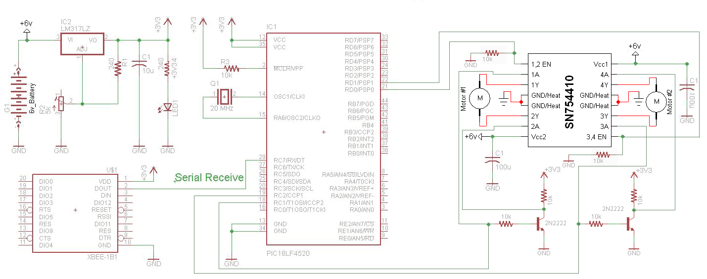
View Full Schematic
SN754410NE Control Signals
Each motor requires 1 enable input and two PWM inputs. We'll use the PIC's PORTD RD0 and RD1 as enable lines and the CCP module's CCP1 and CCP2 will be used to output PWM to the motor controller. Since the motor controller needs to see a differential PWM, we'll use 2 2N2222 transistors, to invert each CCP output and connect it to the SN754410.
Xbee Module Wireless Input
The Xbee receiver will automatically connect with the transmitter and begin receiving data. All data will be received and output via the Dout pin on the Xbee module. The Dout pin is conneceted directly to the PIC's Rx pin so that the PIC can catch the data.